FLOATING
SOLAR RECEIVER
A VLF receiver,
floating by ground and maintained by solar energy
By Renato Romero
Since the beginning of my VLF activity one of my first
goals was to be able to receive natural radio signals directly from my house.
We can't think of a serious VLF monitoring only with spot receptions: country
expeditions are a fascinating experience but the probability to catch interesting
signals is proportional to the reception time spent. This receiver offers a
good sensitivity and a good hum noise rejection, giving the opportunity to do
natural signal monitoring from your house garden (if the electric environmental
conditions are not too bad).
THE ANTENNA
 |
|
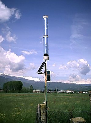
In the picture shown on the left there
is the antenna how it looks when it's finished
and placed in the garden edge. It's composed by a plastic tube (1m long
and with 13 cm diameter), bought in a house building store (for 1,50 Euro
only). On the tube surface an aluminum sheet is rounded, forming two aluminum
cylinder, 10 cm spaced each other (distance is not critical). These two
cylinders form an "on air capacitor" of about 35 pF: this capacity will
be the antenna, used for VLF receptions, and working as an aerial capacitor
probe.
This strange antenna shape gives
some advantages respect to a same length stylus:
a) with a short antenna (the tube measures 1m only)
we have an high capacitance value: about 35 pF
instead of 7 pF
obtained with a 1 m stylus referred to ground. This means high sensitivity
and low frequency corner. We need a 4 m stylus to obtain the same capacitance
value!
b) the antenna can work without ground reference, and
this is another important feature: signal is detected as voltage difference
from an aluminum cylinder to the other. In a classical stylus the signal
is detected as voltage difference from the stylus (working as an aerial
probe too) to the ground reference (normally the soil) |
Although we can choose both different mode with this project
(as floating receiver or as a ground referred) this floating modality allows
to obtain a good receiver separation from the ground influence. In reality we
have never a complete ground separation, but sufficiently high to reject the
hum noise coming from the house. This project, as for the others presented in
this web site, is thought for an home target: I suppose to have an open space,
a garden or a field, and a wire to bring the signal to the PC into my home.
The superior cylinder is connected to a wire which runs
at the center of the inferior cylinder (as in a coaxial cable), and is finally
connected to A point in the circuit. At the inferior cylinder base is connected
a second wire, connected to the B point in the circuit (see electric scheme
next).
THE SUPPLY (SOLAR
CELLS)
Another big problem in an house's garden receptions comes
normally from the power supply. Using as a support the wires coming from house
we bring to the receiver a lot of hum noise. Despite to the high stabilized
voltage we can have with a cheap stabilized power supply, using this energy
we degrade the quality reception: always, because the hum noise run in commune
mode. Main power supply gives unlimited autonomy, but it works as hum noise
vehicle, bringing to the receiver everything we don't want to receive: 50, 100,
150, 200, 250 .... Hz carriers (and not only!). Batteries give a limited autonomy:
not enough to maintain a 24 hours per day monitoring; and I think it's crazy
to replace the battery every day, looking at example at a yearly monitoring.
 |
|
A cheap but functional solution comes
from the solar cells: now available for few Euro (or Dollars) they give
energy enough to maintain the preamplifier during a daylight and enough
current to charge a little 12v lead battery, which works during the night.
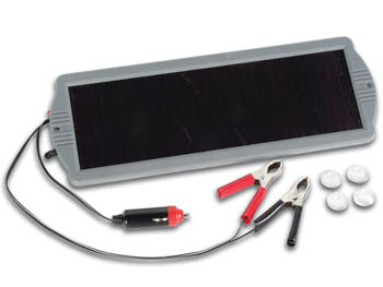
In my project I use a Velleman product
(SOL5N code, cost is about 30,00 Euro) which supplies a 14,5V / 125 mA in
a daylight. The circuit consumption is about 10 mA, then less than two hours
of sun a day are sufficient to maintain the system in energetic autonomy.
My system runs happy since two months and battery
is still totally charged.
|
If you decide to use the same Velleman product,
or others similar, remember to remove the built-in current regulator. It
pulses the current giving a very strong comb noise below 300 Hz. It's composed
by a little chip resined inside the panel; open the panel removing all
the screws and cut the regulator wire before to use it. You can easily
discover if the panel is current regulated: put at the panel output an
headphone, separated by 1 uF capacitor and listen. If you hear a strong
pulse noise you need to remove the regulator.
THE OUTPUT TRANSFORMER
All the works done to insulate the receiver from the hum
noise influence came normally null when we connect the receiver output to an
external line, to connect the garden receiver to the house computer. We transport
the VLF signal to the computer but at the same time we bring the hum noise to
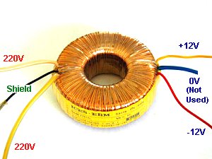
the receiver. A simple but effective solution cames from the use of a toroidal
transformer (eradicated from an old power supply): normally they allow a very
wide band pass from few Hz to many tens of kHz.
 |
|
It appears almost totally
transparent to the VLF signals coming out from the receiver, although it
gives a galvanic insulation. It's important not to forget to connect the
transformer shield (normally it comes as a yellow/green or black wire directly
from the transformer wrapping) to a local ground, just immediately near
the receiver using at example an aluminum or a copper stake in the soil.
It doesn't gives a big contribute to the reception but nulls in the ground
all signals coming in commune mode from the computer line. Then we will
have into the house computer a clear signal, as we was working with a battery
laptop just below the antenna. |
From tests done in my garden (antenna placed 15m far from
my house) the hum noise reduction with a Floating Solar Receiver reaches the
95% in power, especially for the odd harmonics, compared to a receiver in the
same place but maintained by wire and with direct connection to the PC at the
home. The high voltage side is connected to the receiver, shield must be connected
to ground (local ground) and low voltage side to the output line. I tested both
transformer configuration (High/low and low/high) choosing the indicated one
because the output OpAmp of OP07 don't overload: using the low voltage side
as receiver output at very low frequencies it looks as a short circuit, and
that doesn't like to the preamplifier.
THE CIRCUIT:
floating configuration
It's easy and simple to build. The core of the
circuit is the OP07 operational amplifier: it is a very low input bias
current (0.7 nA) and ultra low noise component (0.35 uVpp); these features
make this component optimal for this application, where an high impedance
circuit is required. So we can reach with a short antenna and a single
amplifier stage a wide band receiver (from few Hz to 22 kHz) with an high
sensitivity (about 10 pT, the Schumann resonances strength).
 I
I
Its operation is simple: the left part with TL081 works
as a dual voltage supply only, splitting the solar cells output voltage in a
dual precision and stabilized symmetrical voltage. The battery is a classical
12v lead battery 2 Ah capacity. The right part of the circuit, with OP07, adapt
the high impedance of the two cylinders with the input impedance transformer.
The gain of this stage is the same of the transformer voltage lost, so the entire
circuit has no gain: the voltage at the line output is about the same of the
voltage between the two cylinders. The toroidal output transformer gives a galvanic
insulation from the line output and, by transformer shield wire, put at the
ground the noise coming in commune mode from the house. The line coming from
house must NOT be connected to any earth connection; this configuration gives
a good hum noise rejection.
THE CIRCUIT:
grounded configuration
The circuit is the same for the floating configuration:
it changes the antenna connections only. The two cylinders are connected together
and they are used as a fat mono pole, referred to the ground. The B point, first
connected to the inferior cylinder, is now put to the local ground, with the
transformer shield. As for the other configuration the line coming from house
must NOT be connected to any earth connection.
You can choose this connection scheme if you need
more sensitivity to the frequencies below 20 Hz, and if the hum noise in
your garden is not too high. However results are better than a classic
receiver connected to house directly by wire.
RECEPTION COMPARISON
Since the beginning of my VLF activity I discovered
best results with big antennas respect the little ones. An this in a low
polluted environment, as an house's garden in the country can be.
 |
|
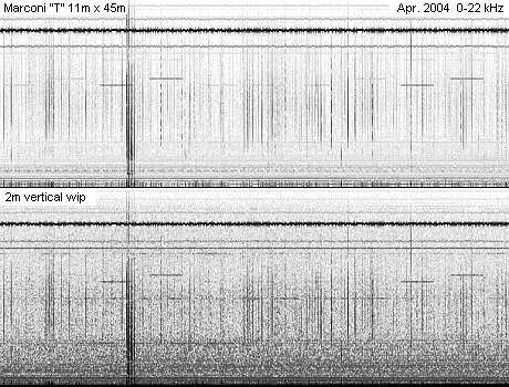
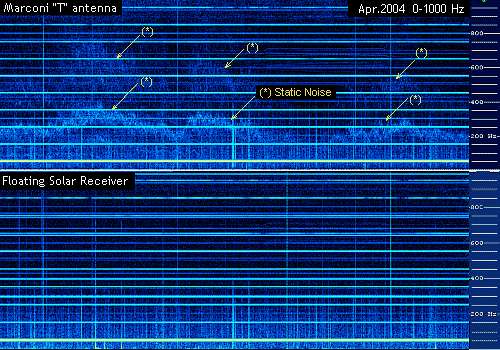
Here beside an example of daylight reception: we
can see the difference between two antennas placed few meters one from
the other: the big Marconi (a "Tee" antenna 11m high with a double 45m
top hat) gives a good reception even if some hum noise is evident at the
bottom of the first spectrogram.
But a 2m vertical stylus with a classical RS4 receiver
receives instead a lot of hum noise, below 10 kHz: I think an easy whistlers
reception became a problem in the second example. And we are at the same
place, antennas are few meters one from the other and at the same distance
from the house. |
The following comparisons will be done placing the
Floating Solar Receiver instead of the 2m vertical stylus on the RS4 receiver
here above tested. Starting from here the project will be tested comparing
the reception with the big "T" results (the better antenna I can use for
this test).
 |
|
A first example gives a substantial equality for the
two receiver: all comparisons are done setting the windows mixer for the
same signal level of the statics and RTTY signals. I think it's the best
mode to evaluate the real noise rejection. RTTY and Alpha appears clear
in the same graph, statics seems identical and hum noise is substantially
the same.
This is a quite good result: we are comparing 1m
tube with a 45m aerial antenna! It's the first time I can see a deign
substitute to my big Marconi.
|
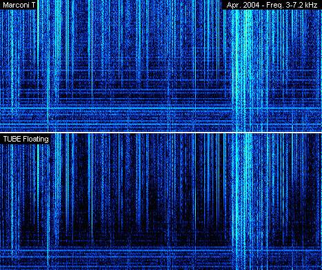
A second example cames in the voice frequency range:
 |
|
Spectrogram shows the frequency range from 3 kHz
to 7.2 kHz, the typical whistler frequency zone.
This picture represents a central zone zoomed respect
the picture before. Here we are the same statics signals (the vertical
lines) and less hum noise (the horizontal lines, a 50 Hz carriers comb)
in the Floating Solar Receiver. This situation is not always true: the
hum noise changes hour by hour and sometimes the two spectrogram appear
more similar than here represented. But normally the hum noise is less
with the floating receiver than with the big T antenna.
|
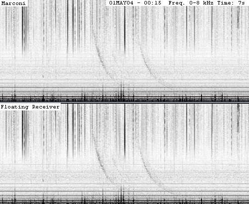
And a third example in a real whistler reception:
 |
|
The picture speaks better than the words: the two
whistlers reception can be considered identical.
In the floating receiver we have few less hum noise,
but differences are very little. |
EXTREMELY LOW
FREQUENCIES RECEPTION
The frequency range below 1 kHz is affected by many specific
reception problems. Here we have a lot of hum noise: normally the principal
quantity of hum noise is just there. We have less sensitivity of the antenna,
because at so low frequencies the intrinsic capacity of the antenna becomes
a super high impedance source and the adapting with the preamplifier became
critical. Natural radio signal at ULF frequencies, like Schumann resonances,
represents more critical reception respect whistlers, tweaks, statics and RTTY.
Besides the rain produces a lot of local hum noise below
500 Hz, caused by static field from ground to sky: when a storm cloud passes
over our heads.
 |
|
Measures done show in a clean sky day an electric
field with intensity of 100 V/m, produced of a superficial negative charge.
When a storm is approaching the situation is reversed: the clouds base is
strongly negative and the electric field at the ground can reaches values
of about 1000 V/m (with a potential difference between clouds and ground
of 2 3 millions volts!). In this conditions a big antenna becomes very
sensitive and very dangerous. The picture shows these signals during a rain:
the Marconi results seriously affected by this problem, the FSR not. |
Another important comparison comes with the Schumann
resonances reception:
 |
|
A floating solar receiver has been compared with the
big T in a Schumann resonances range, and has been tested in both configurations:
floating and grounded.
Here we can see the difference between a big antenna
an a little tube: but FSR don't work so bad. Schumann resonances are distinguishable
in all the pictures: better with T respect the FSR and better in grounded
configuration respects the floating one. Remember: we are comparing 1m
tube with a 45m aerial antenna. |
The situation can be better evaluated looking at the graphs
below: curves are calculated averaging 20 minutes of acquiring. The FSR can
be use with good efficiency down to 12 Hz in floating configuration and down
to 5 Hz in grounded one.
A last but interesting comparisons: on the russian
submarine signals reception.
 |
|
Used as submarine signals receiver the FSR (Floating
Solar Tube) gives the same results of the big Marconi.
In the picture we can observe the 82 Hz carrier received
in my garden: with both receivers the S/N ratio remains the same: 15 dB,
using a FFT resolution of 5 mHz. We can consider the two receptions identical.
|
CONCLUSION
This receiving system doesn't make miracles: probably you
can have same results with a 5m stylus and a portable receiver in a middle of
a country field. Ground insulation is not total: toroidal transformer has its
proper coil to coil capacity and then the receiver is never full floating but
partial only. But the opportunity to have the signal at home directly on wire,
without dirtying the reception, gives a big chance to study this frequency range
with unattended operations. All that without any electronic complication as
optical link, data link or others, but using only a main transformer.
Comments and suggestions to improve this project
are always well accepted! Thanks to Marco Bruno for technical support and
measuring instruments coming from Spin,
and to Andrea Bertocchi for English revise.
Return to the index