

Project Summary
Construction hints
"Bikeloop" antenna is a double magnetic loop composed
by two orthogonal loops. Original project is available at site: www.vlf.it
.
This document describe how the prototype was built,
the purpose is to give some construction hints to people who wants to try
this kind of antenna.
Mathematical and electrical details are well described
on to the site above.
|
|
The prototype has been projected for "on field" usage, and should match the following requirements: light weight, robust, cheap, and not cumbersome.
As support for the copper wrappings we used two
bicycle rims, due to the fact that rims are cheap and can be easily found
and processed.
Two aluminum rims has been used for the prototype.
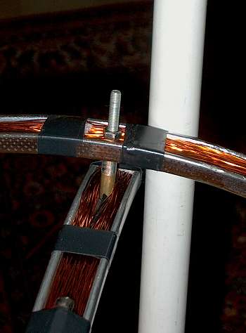
Both rims has been cut and secured together. The
open edge has been put in the higher part.
In the lower part, bushes and sleeves compose the
fixing mechanism; rims are also connected electrically on this side.
In the higher side, rims structure has been fixed
using insulating spacers. Each rim is insulated from the other one.
As written above, sleeves secure rims, this mean
that rims can rotate and get close. This is helpful during transport. The
total thickness of the antenna is only a bit more than the thickness of
two rims.
 |
 |
During the setup of the antenna, before the start of the recording, operator must take care of orthogonalithy of the loops.
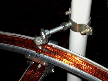
Another important thing to deal with is the physical support of the antenna. It also has to be light and robust, but does not have to interfere electrically with the antenna. To match this requirement a piece of PVC pipe has been used. Diameter is about 40 mm, 1.5 m length.
A metal collet has been fixed on the top edge of
the support. It will be connected to the top of Bikeloop structure by a
long screw. Metal collet has a threaded hole. Bikeloop's long screw will
match this hole.
 |
Several turns of insulating tape have
been wrapped on to the internal surface of the rims, to avoid damages of
enameled copper wire.
Copper wrappings are identical; both wrapped clockwise, and terminated with a RCA connector. We used a 0.7 mm diameter enameled wire (about 0.4 mm^2), and we did 75 rounds for each wheel. Total length of wire is about 335 m. Consider 340 m to compensate the increase of the diameter of coils during wrapping and for an easy soldering of connectors. At the end of mechanical construction two EASYLOOP receiver circuits has been realized, to supply an adequate signal to a recorder or to a PC soundcard. |
For this release of the receiver we used 2 TL081
operational amplifiers, one for each channel.
Both circuits has been assembled on to the same
circuit board, no undesired coupling between amplifiers has been detected.
 |
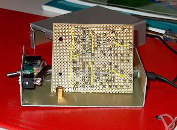 |
OFFSET regulations trimmers have been omitted, because
they are not necessary. In this way TL081 can be replaced with more efficient
OP27 or similar without changes on the circuit board.
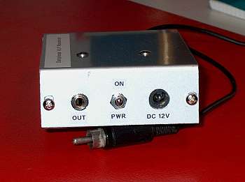 |
Both circuit are powered with a single
12V source. Power consumption is less than 20 mA.
Circuit board has been secured in a metal case. Metal case is connected to negative ground. Please note power connector, on/off switch and 3.5
mm BF stereo line out.
|
Reception Tests
"Bikeloop" antenna was tested on 2002, April 28th
from 08:00 UTC to 09:30 UTC near Prosto (46°19.496'N, 9°26.413E,
province of Sondrio, JN46RH), a little town in the middle of the Italian
Alps.
Main purpose of the session was to test whole system,
to find out weaknesses that need to be corrected.
Weather conditions were scattered, but without
rain since the previous day.
The reception area is not extensively urbanized, so it was not too difficult to find a quiet place to use the antenna, even if the 50 Hz hum was always present.
Antenna was mounted on its PVC mast and fixed about 30 cm above the ground. No relevant metal masses were detected nearby the antenna.
Receiver was feeded with 15V provided by an external
battery pack.
The recording device was a semi-professional DAT
Recorder Sony TCD-7, powered by another external battery pack, for reliable
long time operations.
The loops were positioned orthogonally, oriented
in North-South and East-West directions.
North-South loop was connected to the right channel
of the recorder, East-West to the left channel.
Firsts receptions, not recorded, listened in monitor
mode, pointed out the presence of the main hum noise. Hum came mainly from
the right channel. In background were clearly audible many Sferics.
Some Sferics were very strong.
Separation of channels was great, many signal were recorded on only one channel, depending on the direction of incoming signal, the most powerful ones on both. This recording shows the directivity of the antenna.
Recording level was set to "manual", no compression was activated, and sampling frequency was 48 kHz.
Recording started at 08:15 UTC and ended at 09:00 UTC.
At the end of the recording session we took two
tracks.
First one, the "good" one, consist of 37 minutes.
Second one, only three minutes long, was taken
only to record the interference from my clock, but it showed to contain
something else.
Let's go to discover it!
Data Analysis
After recording session, the first thing we did was moving the recording to a more reliable, robust and easy to handle support.
All recordings has been moved to a standard audio
CD. An optical fiber cable has made the connection between CD recorder
and DAT recorder.
In this way no noise has been introduced on to
the CD, caused for example by cathode ray tube monitor and so on.
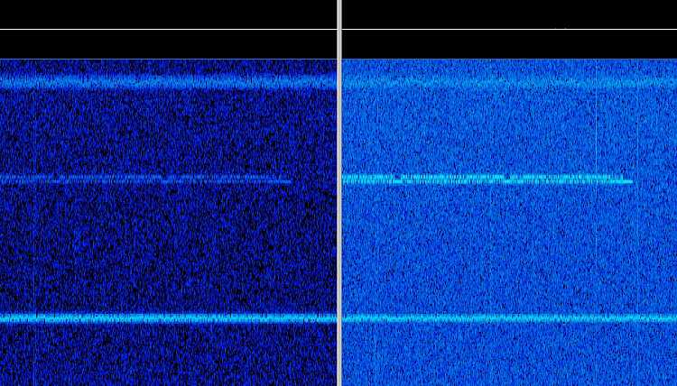
First look show a problem with one of the channels, recording level of one of this seems affected by more noise than the other. Also presence of hum is more evident (frequency scale and range are the default of Spectrogram):
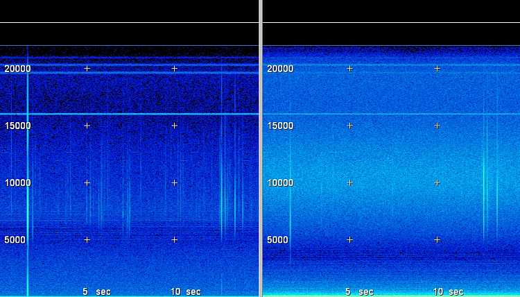
Due to directivity of antenna I can't exclude that
right channel was directly in front of a buried power cable.
Preliminary home tests did not point out a valuable
difference in the performance of the amplifiers, so we are investigating
on this.
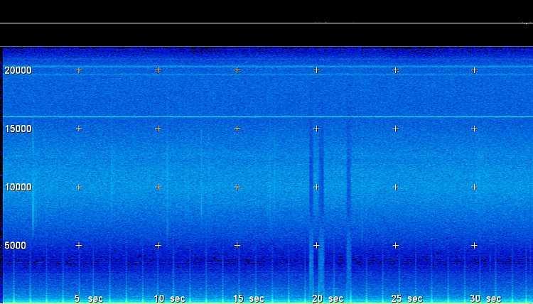
Here comes another spectrogram:
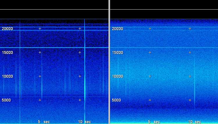
There are more Sferics, two of them are present on both channels.
In the whole recording there are not evidences of Tweeks and Whistlers, so we focused our attention on the "lines" on the top of the spectrograms, one in particular appeared after 24'30'' and disappeared 32'' later. The frequency is about 18 kHz.
The same mark occurred 10' later, for 32 more seconds.
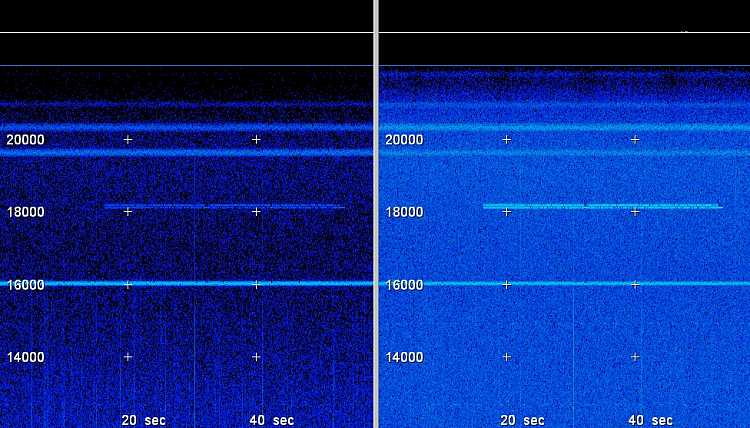
Let's have a closer look at the beginning of the
signal:
The center frequency is about 18100 Hz with a little
frequency shift (FSK ?) of about 50 Hz.
We found out that it could be a Russian FSK transmission;
probably a kind of FSK CW. It's not possible to know exactly the location
of the transmitter (nor the content of the message, of course) because
there is not a CW identifier before or after the message.
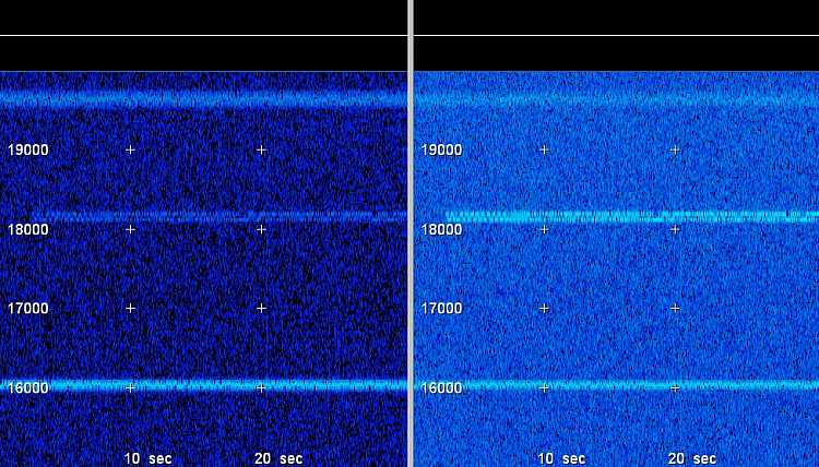
At the end of the message:
It's clearly visible the end of the message, followed
by some kind of AR SK symbol.
The others lines has been identified to be MSK
transmissions; checking out the VLF frequency guide the transmissions has
been identified as follows:
· 16000 Hz: GBR from Rugby, UK, Royal Navy,
MSK.
· 18100 Hz: FSK transmission from somewhere
in Russia, frequency appears to be in use by UFQE. This station is also
reported active for short transmission every 10 minutes, several times
in a hour.
· 19579 Hz: GBS from Criggons, UK, MSK.
· 20270 Hz: ICV Nato VLF Transmitter located
in Isola di Tavolara, Sardinia, Italy, MSK.
· 20870 Hz: Due to the weakness of the signal
is not possible to determine the exact center frequency. If our guess are
right and the center frequency is correct, the station appears to be HWU,
owned by French Navy, located in Rosney, France.
Again, we have no real evidence about the correct identification of these stations, but this was not our main target.
The purpose of this antenna system is not to catch or spy military transmissions, so the identification of the previous station is not sure, the content of the message is not decodable nor understandable at all.
The most important thing is that we received something.
In fact, the main purpose of the test was to check
the functionality of the whole system. Results and impressions are explained
in the next chapter.
False Receptions:
VLF Interferences
generated by electro-mechanical quartz clocks.
Quartz electro-mechanical clocks can interfere with
receptions, especially when reception is done with a magnetic antenna (i.e.
easyloop or Bikeloop).
The crystal oscillator of the clock usually works
at 32 kHz, but its power is very weak and its signal is not usually received.
The little electro-magnet, used to move internal
gearings and hands on the face of the clock beats at exactly 1 Hz.
This causes a typical beat, which can be easily
confused with some kind of time-mark station.
Interference can be listened and recorded from several
meters of distance,
especially if the case of the clock is made by
plastic (not shielded) instead of steel.
Activation of chronograph will produce a funny
tone, due to the fast movement of the hands.
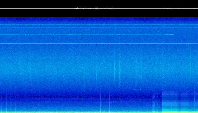
On to the following spectrogram are visible:
· Interferences caused by the chronograph
on both channels.
· The end of the 18100 Hz transmissions.
· Interferences caused by piezoelectric
beeper of the clock, it is drawn like a sequence of four dots at fixed
frequencies.
Its sound is audible on to the audio track.
By the way, during this test clock was exactly in the center of the loops.
VLF unveiled
10 things to
know for receptions and recordings on this band.
More or less one year ago, looking in my old stuff boxes, I found out the unfinished prototype of a VLF receiver. It had been projected by NASA for the STS-INSPIRE experiment, concerning the transmission on to VLF bands from the spacecraft Shuttle.
With the big help of Renato Romero, IK1QFK, and
thanks to the information contained on his site www.vlf.it I finally finished
to set up the receiver...
I would like to tell you something about the most
common mistakes related to the setup of your VLF recording station.
1. If you live in a city you will not be able to
receive anything, due to the high electric noise level. In this case it's
a good idea to set up a portable station.
2. Always feed your receiver / recorder with batteries.
There is no power supply totally free from main hum. Consider also all
the harmonics... a real disaster.
3. Use ground, it is absolutely necessary. I use
to connect my receiver to the ground with a 4 sq. mm wire, which is also
connected to a piece of copper pipe. During operations this pipe is buried
in the ground. Without earth bonding, intermodulations noise may occur.
4. Do not use tape recorders with Automatic Gain
Control (AGC). You will basically record statics and impulsive signals,
AGC continuously modifies microphone gain, creating false recordings and
intermodulations.
5. When using longwire antennas, always suspend
the wires, keeping them insulated from the ground. Do not extend wires
directly on the lawn.
6. Always use shielded cables for BF connections
inside the receiver as well as outside, to connect receiver and recorder.
If you are building your receiver with surplus components, be sure that
all components are working. It's never funny to look for a defective component
at the end of the construction.
7. Provide your receiver with a monitor BF output
and use it with earphones or with a little loudspeaker. Some recorders
have this function, use it, not to discover at the end of the recording
that aerial was disconnected...
8. Audio dynamic of commercial recorders (especially
surplus) is very poor. If you have a portable DAT use it, results will
be better. If not try with equipment you have, interesting receptions are
made sometime with old recorders.
9. Do not stay close to anything who looks like
a main distribution line. AC power noise will be very strong and you will
find out that place noisy like your city flat.
10. Be very, very, very patient. Even if all your
stuff is working fine nobody can be sure to record something interesting.
It's not like switching on your radio and listening to your preferred program.
For example it's very rare to record a whistler in a summer sunny day,
so don't be angry or sad if you do not record anything exciting.
Be brave and don't be scared of initial failures.
At least... have fun, enjoy. A walk in the country, or in the woods, is a good occasion to listen to the song of the nature, with ears and with aerial. It is like to feel the heartbeat of our planet and could become a real exciting adventure.
Results
Bikeloop antenna project involves electronics, physics,
mechanics, atmospheric phenomena and a lot of other things and should not
be intended as a final artifact.
It must be intended as a starting point.
This is the prototype and how it works. Every single
part could be better and could have better performances.
Receiver performances, for example, could be enhanced.
An active filter should help the amplifiers to work better without amplifying
noise.
We used TL081, but it is a quite noisy op-amp,
OP21 and OP27 are much better.
Remember also that every resistor or capacitor
generate noise, so less components means less noise.
Power supply is also very important, because noise
can travel through cables to the amplifiers, and we do not want this.
At the moment we are studying a new all-purposes receiver, with active filters, good for magnetic and electric fields. First lab tests has been done. Stay tuned for further informations.
Recording device is absolutely important. We made recordings impossible to do with an analog cassette recorder, even if HI-FI. Not only for the high audio frequencies involved but also for the amplitude of impulsive signals. The spikes are so fast and powerful that the dynamic of an analog audiotape is not enough.
DAT is the best on market today but it is also very expensive. If you are planning to deal with VLF for a while consider buying a Minidisc recorder. It is cheaper than a DAT but has very good performances.
We did not check yet our recording with other software but should be interesting integrate signals from both channels. A primitive RDF (on every signal present) could be done to find out the direction (+ or - 180°) of the signal.
That's all for now, folks!
Feedbacks are welcome; please contact us at the following addresses:
Claudio iz2fer@tiscali.it
Gabriele gseleri@sente.it
Credits:
Many thanks to:
Renato and Gabriele for the usual technical support,
My dad Roberto for his patience and mechanical
capabilities,
Riccardo for the digital camera.