" ADA" : AN
ACTIVE DIFFERENTIAL ANTENNA
FOR 5Hz 500
Khz
By I1RFQ, Claudio
Re
This article describe the design, construction, measurements and receiving experiences made with such exotic antenna that fully covers ELF SLF ULF VLF - LF and part of the MF. See Table 1 at the end of the article. Connecting this antenna to a PC with a Sound Card and Software like Ciao Radio, http://www.antennex.com/Sshack/ciaoradio/ciaoradio.html, it is possible to receive, analyze and demodulate any ELF SLF ULF VLF signal up to 24 kHz.
STATE OF THE
ART
A lot of antennas for the VLF and ULF use have
been developed so far. A virtual plethora of examples can be found at www.vlf.it.
The antennas at these frequencies are vertical polarized in 99% of the
case. The mode of propagation is the Surface Wave where the vertical wave
could travel. Every horizontal component is mainly cancelled from the anti-phase
reflection of the ground.
Horizontal polarization looks used only to receive
the seismic precursors and the signal coming from the sky wave of the
auroras that have random polarizations. Most of these antennas are based
on the use of Short Monopoles (with or without capacitive hats) or Small
Loops as in Figure 1.
Both of them are typically not tuned. The monopoles
are typically connected to high impedance amplifiers and the loops are
typically connected to low impedance amplifiers as in Figure 2. This allows
these antennas to have very large bandwidth behaviour. The problem with
the monopoles is that the ground system that recreates the lower part of
the dipole is very fuzzy. This means that local currents induced from
the main at 50 or 60 Hz and harmonics could easily flow into this undefined
part of the antenna. This reduces the possibility to shield the antenna
from these high level fields from the main at 50 or 60 Hz and harmonics.
One of the possibilities to avoid this is to use
a short vertical balanced dipole as probe. To avoid the use of a balun
made with inductive parts that will limit the bandwidth, at this frequency
it is possible to use a differential amplifier in the so called configuration
of Amplifier for Instruments. The use of Operational Amplifiers allows
a high level of peak to peak handling and of intermodulation immunity.

Figure 2 : Short Monopoles or Small Loops connected
to Operational Amplifiers for Broadband operation
DESIGN OF THE ANTENNA AND OF THE ACTIVE PART
A short monopole (l < 0.1WL) has an effective height (H) approximately equal to its length (L). The equivalent circuit, connected to the amplifier is shown in Figure 3:
Figure 3: A short monopole equivalent circuit connected
to an amplifier
Ra, that is the radiation resistance, is very low and tends toward zero while the frequency is decreasing and is in any case negligible with respect to Ri, that is, the input resistance of the amplifier. If we apply the Thevenin theorem transformation, we get the simplest possible circuit shown in Figure 4.
Figure 4: Equivalent circuit of the antenna and input amplifier.
The amplitude of the equivalent generator is decreased
from the partition between Ca and Ci, but the equivalent capacitor Ct is
the parallel of Ca and Ci. Ri and Ct state the lower frequency passband
end, Fc. If Ri and Ci are larger, then Fc is lower.
Fc = 1/(2PI Ri Ct)
For example, if we have:
Ca = 30 pF
Ci = 0
Ri = 100 Mohms
Fc = 53 Hz
To arrive to 5 Hz, we have to increase the total capacitance Ct to 300 pF. Since 100M Ohms is a value difficult to increase, going down till 5 Hz could be achieved in three ways:
THE ELECTRICAL DIAGRAM
The basic electrical draw is showed in Figure 5.
The full draw is showed in Figure 6 .
Fig.5 : The basic electrical draw of the Active
Differential Antenna
Fig.6 : Full electrical draw of the Active Differential
Antenna .
The capacitance of a monopole dipole depends from the parameters and the formula showed in Figure 7. The capacitance of a Dipole is half of that of the monopole (it can considered as two monopoles connected symmetrically back to back). In the equivalent single-ended circuit the capacitance that we have to consider is exactly that of the monopole.
Fig.7: Capacitance of a short monopole .
If we want to have an idea of the capacitance of
this antenna with some practical diameters, we can consider 2.5 cm and
30 cm that are the usable practical diameters that could be found on the
market to build a self-supported dipole 2m long, made by wrapping an aluminium
foil on a PVC pipe. Calculations give respectively a capacitance Ca of
15 and 46 pF. If we want to have more capacitance, the use of a capacitive
hat looks unpractical. The capacitance of a hat that is 1x1m adds only
9 pF to the total capacitance. As we learned, the only easy way we have
to have the passband flat down to 5 Hz on the lower corner is to add a
capacitor in parallel to the dipole.
Calculations we have done show that we need a total
capacitance of 300 pF in the single-ended mode. A half value is needed
in the balanced mode (between the dipole terminals), so a 150-pF capacitor
will do the job in both cases, but it is obvious from Figure 4 that the
antenna with the larger diameter will be more sensitive.
Figure 8 and 9 shows the simulation of the equivalent circuit without and with the equalizing capacitance. I think that they are self-explanatory. In any case, this is only needed if we want to go down from about 7 to 42 Hz, range where we have the Shumann resonances (heart that acts like a spherical cavity, excited from lightens). http://www.vlf.it/Schumann/schumann.htm
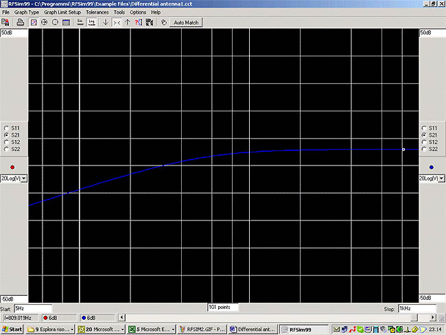
Fig.8: Frequency response without the equalizing capacitance .
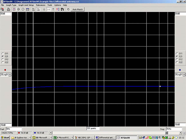
Fig.9 : Frequency response with the equalizing
capacitance .
On the upper frequency corner, if we use the antenna
only with a sound card, it is useful to avoid the possibility of overload
or intermodulation from strong signals on the MW band.
Capacitors in parallel to the resistors of 27k
Ohms, on the feedback of the first three operational
amplifiers, easily do the job (Pins: 1,2 6,7
8,9). Using again:
Fc = 1/(2PI Ri Ct)
A value of 220pF will give a Fc = 26.8 kHz. Having
two poles, the slope will be 12dB/octave.
If someone would like to find the best differential
balance to locally null as much as possible the hum at 50 or 60 Hz, could
change one of the resistors of 27k Ohms connected to the pins 1,9 or 7,10
of the operational amplifier with a series of a resistors of 22k Ohms and
a multi-turn potentiometer of 10k Ohms. Nulling has to be made with the
antenna mounted in his place.
SOME PRACTICAL RECEIVING EXAMPLES WITH ADA + CIAO RADIO
The overall spectrum received is showed in Figure 10. The first part (till around 5 kHz) is fully filled with the industrial frequency (50 or 60 Hz) and his harmonics or switching spurs. In the band 15-24 kHz, there are some strong signals very easy to receive. The first one of this is man made: the horizontal frequency of the TV sets. Please also note a strong carrier also at the horizontal frequency /2 with the same origin.
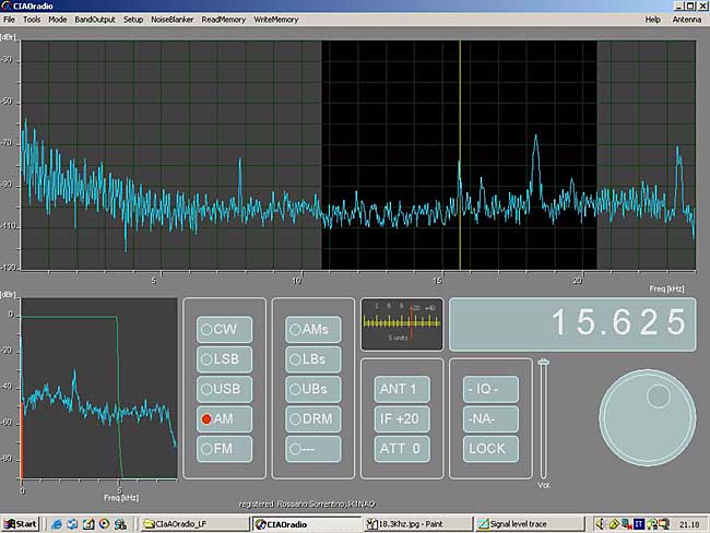
Fig.10 : Overall received spectrum till 25 Khz
. Man made horizontal frequency of the TV sets marked. Note also the strong
carrier at half the frequency .
The other signals are generated from the Military Army and are modulated at 50 baud at: 16.5, 18.3, 19.6, 21.150 and 23,4 kHz. Other signals that can be currently received are the Russian Alfa Navigation System (call sign ZEVS) at: 11.9, 12.65 and 14.88 kHz.
If you carefully see the spectrum, you can see regularly some carriers popping out from the noise. The best way to see them is to use the waterfall option of Ciao Radio as shown in Figure 11. You can recognize two of them on the same screen. To tune one signal, narrow the filters and look at the amplitude of the signal as shown in Figure 12.
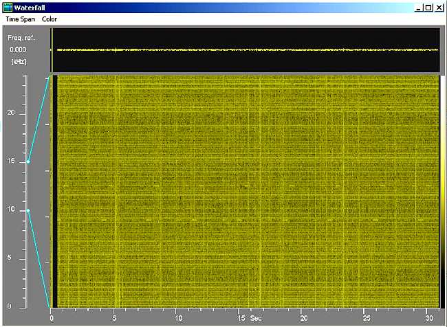
Fig.11 : Two Russian Alfa Navigation System showed
at the same time in the waterfall mode at 11.9 and 12.65 Khz .
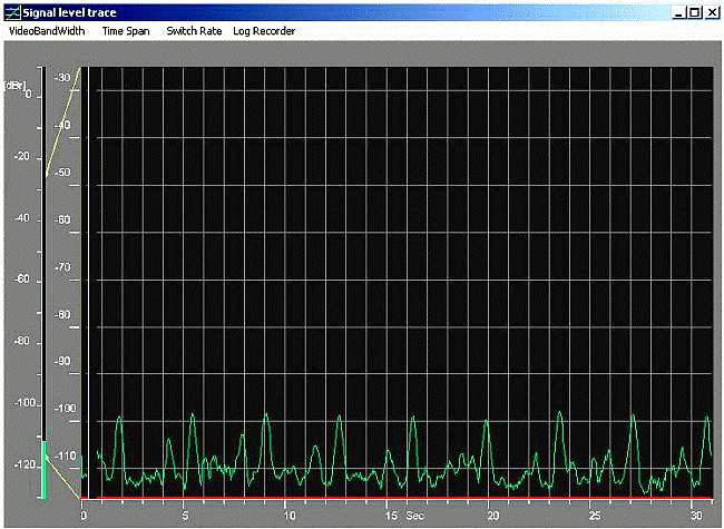
Figure 12: The amplitude of the Russian Alfa Navigation
System at 11.9 kHz, recorded during the time. Transmission occurs around
every 3.5 seconds.
Unfortunately, I dont have the Russian Submarine
plots at 82 Hz, because my tests were done during the couple of months
of black out they recently had, but in this link you can find all the information:
http://www.vlf.it/submarine/sbmarine.html.
US transmission to submarines at 76 Hz ceased a long time ago. US submarines
communicate in full duplex with probes on the sea surfaces
that use satellite links. For more exotic and more
difficult signals to receive, my source of information is again: www.vlf.it
A PRACTICAL EXAMPLE OF CONSTRUCTION
What I have built is showed in Figures 13 and 14.
Please use it as a bad example of how to build an antenna
..I am typically
lazy
.. in any case, it works
.. I was not particularly interested in
the 5-50 Hz band, so for the moment, the element of the dipole was only
3mm of diameter. I am building now a new version, wrapping aluminium foil
on a PVC pipe of 30 cm of diameter, for trying to receive on this band.
My friend Renato Romero, IK1QFK, has reported to receive the Shumann resonances
and the Russian transmission to submarines them with this setup. To power
the antenna, I first used a 9V battery. Now I use a Phantom Power (like
in the microphone systems). See Figure 15.
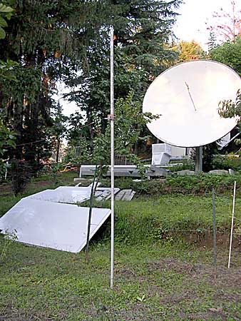
Fig.13: ADA mounted in the garden |

Fig.14 : ADA active circuit To power the antenna , I have use at first a 9V
battery .
|
Fig.15 : ADA Phantom Power supply .
CONCLUSIONS
A simple and cheap antenna to receive ELF SLF
ULF - VLF - LF and part of the MF signals has been reported. In conjunction
with a PC with a Sound Card and the Ciao Radio Software http://www.antennex.com/Sshack/ciaoradio/ciaoradio.html,
it is possible to receive, analyze and demodulate any ELF SLF ULF -
VLF signal till 24 kHz.
Welcome in this exotic world and have fun!
Designation, Frequency, Wavelength:
ELF, extremely low frequency, 3Hz to 30Hz 100'000km
to 10'000 km
SLF, superlow frequency, 30Hz to 300Hz 10'000km
to 1'000km
ULF, ultralow frequency, 300Hz to 3000Hz 1'000km
to 100km
VLF, very low frequency, 3kHz to 30kHz 100km to
10km
LF, low frequency, 30kHz to 300kHz 10km to 1km
MF, medium frequency, 300kHz to 3000kHz 1km to
100m
HF, high frequency, 3MHz to 30MHz 100m to 10m
VHF, very high frequency, 30MHz to 300MHz 10m to
1m
UHF, ultrahigh frequency, 300MHz to 3000MHz 1m
to 10cm
SHF, superhigh frequency, 3GHz to 30GHz 10cm to
1cm
EHF, extremely high frequency, 30GHz to 300GHz
1cm to 1mm
Table 1: Definitions of the Frequency Bands following
ITU