J-M Polard (F5VLB) & P. Newton (GM0EZR)
Our idea was to use the difference between GPS pps signal and DCF77 pps signal to measure the difference of travelling time of the radio wave from DCF, and by the way the altitude of the reflecting layers in the ionosphere.
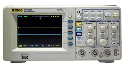
For that we used a NEO-7 module for the GPS pps acquisition and a small module for the DCF77 reception. Thanks to a double channel oscilloscope this measurement is quite easy to do. We will also use a time interval instrument HP5315a from Hewlett Packard to confirm.
Our article is not written to denigrate or criticize the modules presented. For normal use, these are very good modules and we recommend them. For an application like ours, they are not adapted, that's all.
Theory
DCF77 is a time radio station working in the vlf band at 77.5 kHz. A radio wave can be received in direct line or bouncing on the ionosphere layers. If you are located at +/- 500km from the transmitter, the ground wave is prominent. Between 600 to 1100 km the wave received bounced on the ionospheric layers.
The higher limit, during day, to have only one bounce is 1900km if the d-layer is at 70km and during night 2100km if the bottom of the reflective E-layer is at 90km.

Example of
a configuration
If we can measure the time the wave uses to bounce and arrive to us, versus an accurate time we will be able to calculate the altitude of the bouncing layer.
The wave of DCF77 is delayed because it has to make a longer travel to reach us if it bounces on the ionospheric layer. One pulse sent from Mainflingen takes, for a direct wave at ground level, 3.46ms to reach Peter, located 1068km from the transmitter. If the same wave bounces on the d-layer (or the e-layer) at a height of let’s says 90km, the total length of the travel will be 1083km and so the time to travel will be 3.61ms. A difference of 0.15ms. Can we measure that ? and confirm the value ?
Equipment used and preparation
DCF77 module
The DCF module is sold by Universal Solder. For use in Europe it is perfectly suitable as we are not far from Mainflingen. The main data copied from their site are :
| – wide
operating voltage range 1.5 to 5.5V – 60 mm long antenna – current consumption only about 50µA – super high sensitivity of 0.4µV (RMS) – power down control pin – fast start-up – AGC control on/off. It has a crystal of 77.5kHz and an IC type the MAS6180C receiver IC. |
 |
 |
 |
The assembly of the system 77.5 kHz together with a module 60 kHz for MSF from the same supplier. (P. Newton picture)

The GPS module NEO-7
 |
 |
 |
 The oscilloscope Rigol DS1052E |
 The time interval controller HP5315A |
 |
 |
| The HP5315A ha a time interval function (TI A>B) and a TI AVG enabling us to measure the time interval between two signals. | Sample of a measurement of the TI between GPS and DCF with the HP5315A. |
53.23 ms difference… quite a lot !
Location of the receiver vs the DCF77 station
P. Newton is located near Edinburgh in Scotland. The distance to DCF77 is about 1068km. (source https://www.facebook.com/groups/VLF.ULF.ELF/)

The calculation sheet

As told before the flying time at ground level is 3.56ms and by air is 3.61ms.
The measurement
We collected the pps of the GPS (yellow) and the DCF77 module (blue) and do the setting of the oscilloscope to measure the difference in time between the two pps.
The measurement variates quite a lot from 40 to 50ms, but this is just to limit as the variations can be longer
 |
 |
| 40ms difference | 50ms difference |
If we consider these values as correct we will have a distance of more than 11000km for the travel, which is not right.
The GPS signal is corrected to be accurate (else one will have errors of distance on earth). So we have to check the DCF signal.
Reading the data sheet of the chip used for receiving the data we have this diagram.

Note 1 : the crystal is not ovenized and so subject to variations
Note 2 : the agc introduce a delay, as well as the filtering
And we found this table giving the min and max limits for the DCF77 output pulses. Min 40ms and max 130ms.

Searching on internet we found this table about the possible error of DCF versus GPS. We are now ascertain, the error is known and quantified. Our tests showed the same values.

It will be useless to continue with the DCF modules, even if they are perfectly suitable for common use.
The long delay is caused by the way the DCF77 receivers demodulates the signal. They use AGC, RC filters... and all these things add delay.
Given the accuracy of this system, it can be used for VLF reception systems, such as time synchronization, because the sound card does not require much greater accuracy. Thus, in the article, we highlighted the difference in precision of a DCF or MSF signal compared to a GPS signal, but also because a signal with an accuracy of 50 ms is sufficient, by example as a reference, for a low frequency VLF signal.
An idea is to try to measure the delay between PPS and receiver output while tuning the DCF77 in USB mode. We should look for the delay between PPS edge and the sine amplitude change. Maybe using a signal level meter or a sdr dongle.
More to come ….