MAGNETIC ANTENNAE
FOR ULF
Detection
and recording of Schumann resonances and other electromagnetic phenomena
at frequencies below 50 Hz.
By Hans Michlmayr
The emphasis here is on the detection of natural
electromagnetic radiation , with my particular interest being the Schumann
Resonances from 8 ....... 45 Hz. Schumann resonances are generated by the
numerous lightning discharges around the world, injecting shock energy
into the spherical space ("cavity") enclosed between the earth's surface
and the ionosphere. This mechanism is much the same as generating microwaves
within a metal cavity,like a waveguide, by means of small electric spark
discharges (spark transmitter).The earth-ionosphere cavity is physically
extremely large, therefore its resonant frequency is not in the microwave
region, but virtually below the audio frequencies.The fundamental frequency
is ~ 7.8Hz , with several harmonics and other "wave-guide modes" making
up the range of 7.8, 14, 20, 26, 33, 39 and 45 Hz.The height of the ionosphere
varies according to the (local) time of day, etc., and this alters the
exact frequencies. The Schumann resonances are fairly broad, unlike man-made
signals, which are normally nice and sharp. The reception of Schumann resonances
proved to be surprisingly difficult, and in the course of the efforts to
build equipment capable of reliable performance a number of systems were
constructed and operated . These are out lined as follows, together with
technical details and observational results.
THE ANTENNAS
One is simply a loop in the ground. A 40-core telephone
cable was buried in a 400mm deep trench, shaped as a 25 x 53 metre rectangle.
 |
|
All the cores are connected in series (with a centre
connection after 20 turns), resulting in a rectangular coil of 20 + 20
turns, with an effective window area of 53,000 squ.metres. The overall
loop inductance is 427mH, total resistance 546 Ohms. Although it is capable
of picking up signals up to 25kHz into the VLF region, its principal use
is for frequencies below 50Hz.
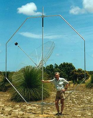
Next I constructed a 200 turn, 4m dia. "Octoloop"
(left image). Its effective window area is 2650 squ. metres . The winding
was made with a length of 100 pair telephone cable, several groups of cores
can be selected to function as a 30 turn up to a 200 turn coil.
The Octoloop was operated at various times as high
as VLF, and as low as 2 Hz. Its principal use was the range 1 - 8 kHz,
but more recently it was actually my first antenna with which I was able
to detect and record the Schumann resonances.
The major drawback of the Octoloop is its sensitivity
to slight movement by wind., causing "microphonics" . |
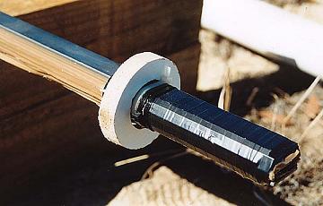
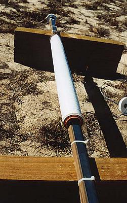
Finally I had to construct the type of device with
which the "professionals" use to study the Schumann resonances, namely
a large induction coil.
 |
|
I wound my coil of 69,300 turns on a 800mm length
of 50mm dia. PVC pipe, using along threaded rod through the coil former
(pipe). This was at one end clamped into the chuck of an electric drill,
which in turn was held in place in a bench vise. The opposite end of the
threaded rod was located through a hole in an improvised bearing bracket
bolted to the workbench. Finally the rod's end connected to a mech. turns
counter. The electric drill was powered by a VARIAC transformer, the best
voltage for my particular drill turned out to be around 60...70 Vac. I
started and stopped this set-up with a foot switch. It took several hours
of continuous high speed winding to get about 8Kg of 0.3 mm dia. enamelled
copper onto the former. |
The finished coil's resistance is 3.64 kOhms , its
inductance 10.52 H .
10 lengths of 3mm thick flat steel bar of various
widths ( 16...40mm) , each 2 metres long, were then put through the pipe
centre to increase the coil's magnetic permeability.
 Click
on the picture to view full screen circuit.
Click
on the picture to view full screen circuit.
|
|
This steel mass just about fills the available
clear inside coil aperture completely. I could not measure its final inductance,
but I guess it must be several kH (!!). The steel bars are insulated from
each other, similar to transformer steel laminations.The finished assembly
was then enclosed in 90mm dia. PVC pipe and endcaps forweather protection.
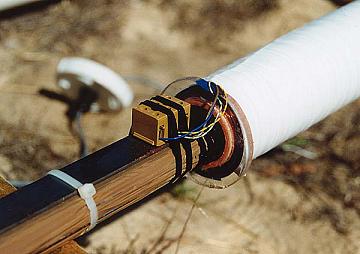
Each antenna has its own pre-amplifier and signal
conditioner , powered by two 12V / 18Ah sealed lead acid batteries, which
are recharged weekly. All signal out-put cables go ~ 70m underground back
to the house.
In the picture beside: Standard low
noise 0-50 Hz field preamplifier. |
BACK-END SIGNAL
PROCESSING
The signals can be directly switched to the output
buffers (13dB) or filtered via low pass and / or high pass filters. Each
filter consists of a six pole Butterworth type, switchable in 10 steps,
a feature which can be helpful at times.The final output normally drives
the line-in socket of the PC's S/B card for signals >5Hz. Signal analysis
is done with the aid of SPECTROGRAM, a very useful spectrum analysis program
(freeware).
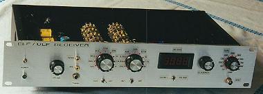
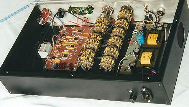
SIGNAL PROCESSOR
Front view and rear/inside
view |
|
 |
Around the clock monitoring can be implemented by
running a screen capture graphics program in the back-ground (as decribed
by IK1QFK) called 20/20, which is also freeware. Each spectrum screen display
is automatically saved at selectable time intervals in the form of .jpg
files for later viewing.
I also use a standard A/D converter from PICOTechnology
, the ADC-11, which is a 11 ch. 10 bit converter. This ADC is packaged
within a DB-25 plug shell and connects directly into one of the LPT- ports
of a PC. The software is called PICOSCOPE , which also contains an audio
spectrum analyzer screen with selectable FFT formats, etc. I mostly use
this for observations below 20Hz.
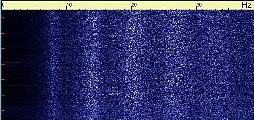
SCHUMANN RESONANCES
RECORDINGS
Detection and recording of Schumann resonances
proved to be more difficult than first expected. Initially I wanted to
use the large ground loop, but never managed to see even the slightest
trace of the Schumanns. Renato (IK1QFK) showed me that it was almost impossible
to receive them with horizontal loops. Vertical polarization was required;
this needed a bit of a re-think..... That's why I built the 200 turn Octoloop,
which made Schumann resonance detection possible. But due to loop microphonics,
reasonable interference free reception is only possible when there is not
much wind. Finally the big induction coil was built; this enables reception
unaffected by weather, but (there seems to be always a "but") daytime operation
is still riddled with some forms of interference. I call this collectively
" human activity" . Because during the early evening hours the various
low frequency spectrum spikes (~2......25Hz) slowly disappear and during
most of the night clean spectra are recorded.
 |
200501-1625
Beside is a comparison trace between the induction
coil and the 200 turn Octoloop. See the low frequency spike below 25 Hz.
Recorded with PICOLOG and ADC-11 device |
 |
Another comparison trace between the induction
coil and the 200 turn Octoloop
A similar recording made with SPECTROGRAM in line
graph mode |
 |
28 Apr. 2001
Also tried recording with SPECTRAN, showing first
5 resonances. |
Throughout the experimentations with Schumann resonance
reception it was always obvious that the weather had a profound influence
on the quality and appearance of the recordings, at least in my location
here. This may well be tied in with the presence of H.V. power lines within
a km of the sensing coil(s). So far I never had the opportunity to escape
into the remote Australian interior with my induction coil and PC, and
make a few days worth of recordings , but I'm tempted !!
In my web site you can find many examples to illustrate
the reception problems like strong winds, rain and other problems (http://wavelab.homestead.com)
ULF INDUCTION
COIL: COSTRUCTION NOTES
In principle the construction of a high inductance
coil seems straightforward; lots of turns of thin wire wound onto a large
coil former.............
 Sketch
showing end view of coil and steel core
Sketch
showing end view of coil and steel core
|
|
Reality of course is always a bit different,
and initially several questions arose: how big , how many turns of wire
and also the shape factor of such a coil. Searching around in professional
publications did not turn up much else except the statement of "30,000
turns". Well, that was a start anyway. The required physical size was never
found in several web searches, except for one. There a fairly small coil
was used, in fact several coils together in an assembly. Life is often
strange, and I found a very professional amateur in my general metro area
who made a real masterpiece of an induction coil; he is using it for geomagnetic
and seismic applications. The construction of his 100,000 turn coil is
described in detail at his site: http://members.iinet.net.au/~ajbv/Magnetic/Magnet.html
That site should also be of considerable interest
to seismic and very low frequency acoustic phenomena researchers...........
After studying the material at his site and a meeting with him, I decided
to make a similar coil. The added interest was that we could both compare
our results over a reasonable distance (~100km).This is a good distance,
not next to our own backyards, and also not on a different continent !
Next the coil former was constructed. This was simply a 800mm length of
50mm dia. electrical conduit. The high impact PVC type (orange colour).
The end flanges are 50mm I.D. an ~ 85mm O.D. , made from 6mm thick acrylic
sheet. |
This coil former then had to be mounted in
a way so that it could be readily driven by a speed controlled power drill
when winding the wire on the former. I used altogether ~ 9.5 kg of 0.3
mm dia. enamelled copper wire.
The winding was controlled by supplying power to
the drill from a VARIAC, set to ~ 65Vac, switched on/off by a foot switch.
After a bit of experience it was possible to wind the wire with amazing
speed, in the order of several hundred r.p.m. No attempt was made to layer-wind
the coil, considering there is no need to worry about high layer-to-layer
voltages (only up to a few hundred uV), and conserving coil winding-window
space was not an issue in this case.
Close-up
of iron ' laminations' (up) of coil end, and connections (right) |
|
 |
The whole winding was tapped at 31,500 turns; subsequently
no use was found for this tapping point (so far).. No more wire was left
after ~ 69,300 turns, so the coil was finished then.The total coil resistance
was measured as 3.64 kOhm, the inductance 10.52H.
 Picture
of complete coil assembly
Picture
of complete coil assembly
|
|
The coil was then tried out and found to be quite
"deaf" , something I was almost expecting.........A bit like building a
radio with a ferrite rod antenna, but only using the coil without the ferrite.
A huge chunk of ferrite material was never an option for this project,
but ordinary steel should be ok because of the low frequencies. The best
material would have been transformer laminations, but not with the required
shape factor for my coil. The next best thing was considered to be 3mm
thick steel "flat bar", which had to be insulated from each other simply
with packing tape, to act as a bit of a barrier for possible circulating
("eddy") currents. Some may think inserting a steel pipe or even a solid
round steel bar would do the trick; but this will act as a shorted turn
(secondary winding) and absorb a lot of signal from the coil !! As
the coil former inside aperture is round instead of square, several different
widths of steel bars are stacked so that an approximation to the circular
shape is achieved. The overall length of all the bars is 2 metres.
Adding the steel core made an unbelievably large
increase in sensitivity. Receiving Schumann resonances was instantly possible.
There was also a significant improvement in the ratio of weak signal to
mains power noise observable. The upper frequency limit of the whole assembly
is surprisingly high, in the order of several hundred Hz , but in this
case it was limited to ~ 150Hz. |
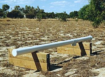
Finally, the coil assembly had to be enclosed within
a removable PVC pipe cover, made from 90mm 'stormwater' pipe & fittings.
(This would of course not be required for coils operating indoors).
Other technical project details and spectrograms
can be found at my web page:http://wavelab.homestead.com
Return to the main index