by Matteo Bruna
Large Induction Coils, probably the hardest and
more expensive way for "home researchers" to study ULF signals. But this
antennas are also the only way to get great performances in magnetic field
measurement with very poor technology. So let see how to build an induction
coil and what can be done to optimize cost and material's efficiency by
applying coil's theory.
The System
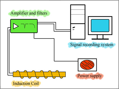 |
The purpose of this work is to create a partly-automatic station for ULF monitoring. To do that a basic system must be formed by at least four elements: the antenna to receive the signal, electronic circuits with their power supply and a system for signal recording and analysis. |
Induction Coil
Loop antennas are divided in two categories: aircrew
loops and induction coils. The first ones have great sensitivity thank
to their big area, but it can be quite hard to construct the structure
to support this loops and keep them stable... moreover very big loops can't
be transported in order to find a good place for their placement. On the
other side induction coils are more difficult to construct and surely more
expensive due to the great quantity of copper required... but their compact
dimensions, which make them easily transportable, and their great sensitivity
make them a good choose to take into consideration.
The Core
The great sensitivity of Induction
coils is due to the high magnetic permeability of the material used to
build the core. This material can be very expensive (try to search for
mu-metal or permalloy on internet and you'll see!). But first of all we
must consider the propriety of this coils in order to correctly dimension
our project and get the best performances from our expensive
metal.
 |
When we
construct coils like these we must consider that they haven't an ideal
behavior. The graph on the left shows that the apparent magnetic permeability
of a cylindrical core can be different from the magnetic permeability
of the metal of which is made. In fact the apparent permeability depends
on the geometric dimensions of the core, in particular on the lenght-to-diameter
ratio. So before buying the metal for the core we must ensure that
we can made the core with the right lenght-to-diameter ratio to get
from it all the permeability that can give.
The metal I choose for my coil's core is magnetic steel used for the construction of electrical transformers. It has a permeability around 1000, so I built the core with a lenght-to-diameter ratio around 50. |
A variable magnetic field in a conductor material
makes currents to flow. These are called Foucault's currents and will surely
flow also in our core absorbing part of the signal we want to receive.
There is no possibility to eliminate this phenomenon, but it can be limited.
The only way is to "cut" this currents by using materials with a high internal
resistance (composite alloys) or to build the core with many little pieces
of metal (bars or laminations) insulated from each other. The magnetic
steel I used is sell in insulated foils, so, to build my core, I simply
put many of these together trying to obtain a cylindrical shape to completely
fill the free space inside the coil. The procedure is also well shown by
Hans Michlmair in his article
.
| To save money I got the magnetic steel from the discards of a transformers factory. Naturally it wasn't already in the right shape so I had to cut it in order to get foils narrow enough to fill the core's volume. At the end were composed four bars with a diameter of 4.5 cm and 70 cm long, that linked together forms a core of about 280 cm, so, with a lenght-to-diameter ratio of about 56. |  |
The Coil
Now the core is completed and it has the right dimensions
to a complete exploitation of the material's characteristics. The next
step is to build the coil... but how many turns? How many layers of wire?
How to wound all that copper? So let's try to answer this questions by
analyzing the physical properties of coils.
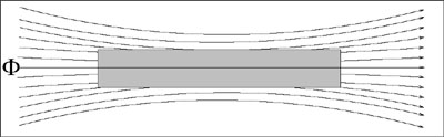
| As shown in the first picture
the core concentrate the flux of B mostly in the his center. So a loop
of wire in the center of the core will capture more flux than one at the
end of the core. But we can't wound all the turns of copper in the center
of the coil because the radius of this turns will rapidly increase... and
increasing radius means more copper... more copper means more thermal noise...
and more cost! So we must try to find the optimal wire distribution to
get the higher flux-to-noise ratio. In the second figure you can see the
mathematical analysis of this parameter... the best performance is achieved
when the coil's length is about 60-70% of core's length.
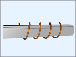
Another thing to consider is that the great number
of turns required creates capacitance which causes the coil to self resonate
limiting the usable bandwidth. In order to limit this capacitance the winding
technique is the scramble winding, therefore turns are wound not
so closed each other as you see in the third figure. This technique clearly
requires a higher quantity of copper, but its advantage in terms of capacitance
reduction makes scramble winding the most used technique for coils
construction. Moreover, with this technique turns of wire can be distributed
in a pseudo random, this allows to wind the turns very fast with a great
time saving.
|
|
Construction notes
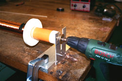
After having calculated the best shape, the construction
of the core is very easy... but for the coil could a little more difficult.
The best way to wind the wire is by using a lathe... but it could be hard
to find one big enough. As seen in Hans Mychlmair's article it's possible
to build a simple lathe with a couple of supports ad a drill. I Choose
a 0.3 mm diameter enameled copper wire because I think it's a quite good
compromise in order to keep the coil's resistance low and be able to make
many turns.
 |
 |
|
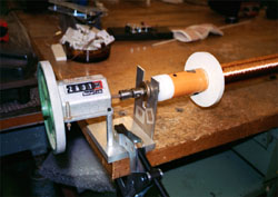 |
For the construction of my coil I luckily found two volunteers to help me. One volunteer had to control the electric drill, the second had to help the wire being unwounded from the big coil of copper bought in a factory and I had to distribute the turns as a scrambled winding. The help of my friends has been very useful... in fact the great problem encountered was that the high weight of the coil bought in the factory (20 Kg!), always risked to tear the copper wire. The work of three person permitted to avoid this risk and the coil was ready in few hours, but I think that with more time and a little bit of care could be possible to do the entire work alone.
In order to give the coil self stability every about 20000 turns it was impregnated with a resin based glue. Then, by few holes in the plastic flange, 6 signal taking were made just to have the possibility of a complete study of the coils behavior.
The following table shows the summary of the coil's construction, with all the operations made in relation with the number of turns wound.
| Number of Turns | Resistance (kOhm) | ||
| 40402 | Signal 1 | 1.59±0.01 | |
| 40662 | Resin Glue | ||
| 61082 | Resin Glue | Signal 2 | 2.52±0.01 |
| 80486 | Resin Glue | Signal 3 | 3.34±0.01 |
| 100384 | Signal 4 | 4.38±0.01 | |
| 110200 | Resin Glue | ||
| 126010 | Signal 5 | 5.80±0.01 | |
| 145012 | Resin Glue | Signal 6 | 6.92±0.01 |
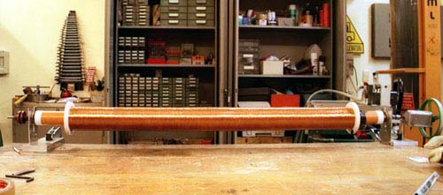
After this, a structure of plastic pipes has been
thought in order to protect the coil from water and humidity.
 |
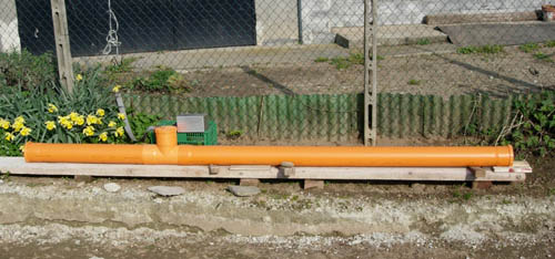 |
Then you should find a place far away from electrical power lines and metallic masses to place the antenna... but this is not always possible as you can see in the second picture, so it's important to amplify and filter the signal from the strong human noise the antenna will receive.
Measures
After having built the coil and the core I've tested
them in many ways. The aim is to analyze their behavior and to measure
such important parameters like the inductance and the parasite capacitance.
There are many methods to do that, but after having tried a few, I chosen
the analysis at low frequencies for the inductance and at high frequencies
for the capacitance.
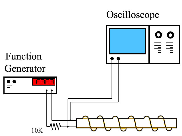
| The
coil has been excited with a function generator and the output voltage
was measured with an oscilloscope as shown in the image on the right. It
is important to make this tests in a low noise place, because the coil
always does its work receiving many signals, especially strong man-made
noise which may compromise the test.
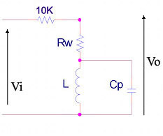
A simple model for the coil and the test equipment is represented in the second picture. Rw is the resistance of the wire, L the inductance and Cp the parasite capacitance. According to this model, if we excite the coil with an extremely low frequency, Cp is turned into an open circuit so we have this expression for Vo: Vo=Vi(Rw+XL) / (Rtot+XL) where Rtot is Rw+10K and XL is the impedance given by L. On the other side, at high frequencies the inductance behaves like an open circuit so we have Vo=Vi(Rw+XC) / (Rtot+XC) Now, measuring Vo and knowing the value of Vi and Rw we can easily find the values of XL and XC from which we can get L and Cp. For my coil I measured an inductance of L = (7.637 ± 0.5)kH and a capacitance of Cp = (2.8 ± 0.5)nF. In order to verify this values, they've been simulated with a Pspice model for the coil, and the simulated behavior has been compared with the experimental observations. You can find the results of this test in the third and the fourth pictures (click to enlarge). As you can see the observed behavior matches the simulation, especially for low frequencies, which is the main range of interest for this research. This values are useful for example for a Signal/Noise consideration as you can find in Renato's work "Minimal Loop" or in general to understand and predict the performances of the antenna. This test tells also that the electrical model we considered for the antenna well represent its behavior at low frequencies, so it can be used for Pspice simulations when projecting the preamp. |
 |
|
 |
||
 |
||
 |
Electronics
The natural signals we want to receive are much
weaker than the human made noise produced by electric power lines. Therefore
the signal from our antenna must be amplified and accurately filtered.
In order to clear the signal, I thought a circuit made of three parts.
The first stage is the amplifier, in fact for a good Signal/Noise ratio
it's important to amplify the signal at first. The second stage is the
50Hz notch and the third a 100 Hz low pass active filter.
The amplifier stage is simply made by one op-amp in the usual inverting configuration. Thanks to the virtual ground of the op-amp, the coil is short-circuited giving the antenna many advantages in terms of noise and bandwidth response. You can find the complete theory in many articles in this web site.
|
||
| After
the amplifier I put the 50Hz notch filter. I wanted a filter with the most
ideal response as possible in order to eliminate only the 50Hz noise and
not the interesting frequencies, and after many simulations I found this
scheme. The cutoff frequency is set by the R-C system in central part of
the scheme and to set it precisely at 50Hz it's important to measure the
real value of resistances and capacitors and choose the best ones. The
most important thing to have a useful circuit is to put a potentiometer
for Q-setting as you can see in the right part represented by R4 and R5.
With this you'll be able to change the wideness af the band rejection and
find the best value for your recording conditions.
NB. The output signal is taken at the output of the first op-amp |
||
|
For the lowpass filter I built a simple 6-th order Butterworth filter with a cutoff frequency set around 100 Hz. I choose this value because it is important to have a passing band which can let you notice of the presence of mirrored signals. Some human made noise signals in fact are produced by the modulation of the 50Hz, and are shown on a FFT graph like two signal at the same distance from the 50Hz... with a passing band from 0 to 100 Hz it's easy to see and ignore this useless signals. In the end, the Butterworth approximation has the advantage of a totally flat response so it's the best configuration for this kind of recordings since I'm not interested in phase information. |
|

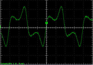
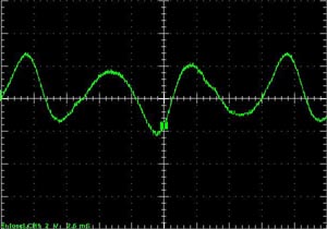
| The stripe down below shows the effect of the circuit | ||
 |
 |
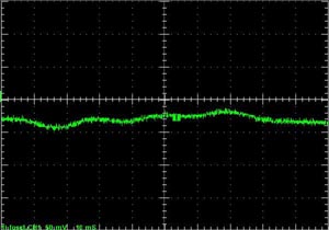 |
| This image shows what you could see by connecting your antenna to an oscilloscope. 50Hz and 150 Hz frequencies appears in all their strength. | Here you can see the signal after the work of the 50Hz notch filter. | And in this image the signal after the third step of the circuit. The bigger sources of noise has been deleted and the signal left can be analyzed or amplified more. |
Recording Examples
Now let's see if all our work was worth! Here you
can see the first two recording tests
|
|
 |
|
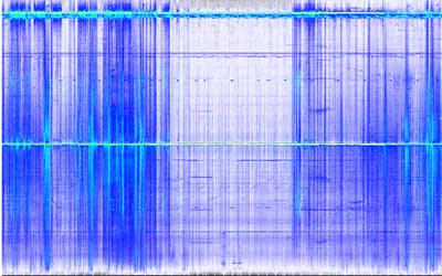
| The second spectrogram has been recorded on the 2-3 march 2006. In the night between SR are a little stronger than in the previous recording, but human made noise is always predominant despite the strong electronic filters used. This means that the place chosen to set the antenna is too near from electrical power lines and noise sources. | 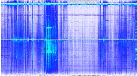 |
Conclusions
This work doesn't want to add anything new to the low frequencies research. It just shows the steps and the reasoning I made to build my ulf antenna... from here the real research work can start. But if there is a thing that this project clearly shows, is the importance to find a place far away from noise sources in order to receive clear signals... unfortunately I don't live in a desert (such a queer thought) and, to analyze data, a pc is needed! So I think that my next research step will be to find a way to transmit the signal from the antenna to the pc via radio. In fact, in the conditions described, this large induction coil has not shown performances better than the minimal loop described by Renato Romero in this web site. This kind of antennas have great potential but it's important to find the best condition to exploit all their power... otherwise because or their high cost, they are unfit for ulf home observation.
Many thanks to:
Prof.Luigi Busso facoltà
di Fisica, Torino.
Renato Romero for technical
support and the nice evening spent talking of the vlf world in front of
a beer!
Ing. Andrea Ghedi for his
help and kindness.
Return to the index