considerations about the use of balanced active antennas
by Pierluigi Poggi IW4BLG
 |
|
This article is a
natural consequence of that about balanced antenna
for VLF, this time no longer investigating the
antenna itself, but its "relationship with the
surrounding world." We take a moment for the "train of thought", that is, the reasons that led us to develop an active antenna for VLF and ELF of balanced type. The "classics" electric field sensors (like "audio antenna") are typically characterized by: sensitivity proportional to the equivalent heigh receiving only of vertical polarization useful band "limited" at the lower frequencies, also due to the "microphonics effect they suffer". These characteristics “complicate the life” of those who want to go "beyond listening," but do real study of the signals. |
The balanced short dipole
The balanced antennas, as we have seen, have built-it the theoretical capacity to overcome these limitations, at least for the most part. It must, however, be installed and connected correctly so as not to frustrate all the advantages.
To get to the general case, we will take a cue from a series of experiments made on the dual polarization antenna, already published on these site.
From the first recordings made on the field, comparing the two polarizations there were no significant differences. Then here came the question: am I really getting into the differential? An important confirmation came from an exchange of views with my friend and expert Renato IK1QFK: he confirmed that the horizontal and vertical fields (electric or magnetic) have to be received very different, such as shown in the following spectrograms .
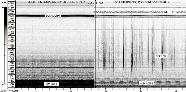
Magnetic
field picked up with a multiturn loop: from 0 to
24kHz, horizontal polarization on left, vertical on
right
On the first field testing with my antenna I did not receive signals significantly different between the polarizations, as well as the levels was changing together with the changing the height from the ground of the receiving structure. It was clear: in spite of the antenna structure, the reception was not the in the differential mode!
Who will ever be responsible?
As with all the differential structures, the "culprit" in these cases, is an insufficient CMRR!
Before go further in particular, let see a small explanation.
The common mode rejection ratio CMRR or (acronym from: Common-Mode Rejection Ratio) indicates the tendency of a differential amplifier to reject signals that came to both inputs. An high CMRR is important in applications where the signal of interest is represented by a small voltage fluctuation superimposed to a voltage offset (potentially large), or when the relevant information is contained in the potential difference between two signals.
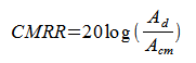
To calculate the CMRR, you must first define two gains as follows:
Ad differential gain, ie proportionality between the output signal and the difference of the inputs

Acm common mode gain, ie proportionality between the output signal and the common level of the inputs

where Vo is the output voltage from the amplifier, V+ and V-, the two input voltages Vs and the input voltage applied in equal measure to both inputs.
The CMRR, which is measured in decibels, is now defined by the following equation:
The real world
Let us now see with the help of an illustration, a typical situation of reception:
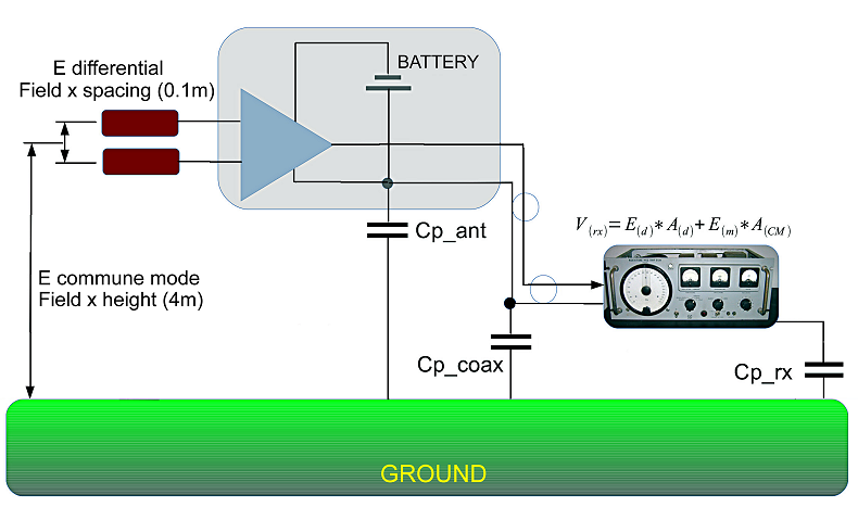
Receiving
field setup scheme
The antenna is considered 4m above the ground, the sensors vertically stacked and spaced 100mm and the receiver powered by a coaxial cable.
Doing a little of accounts, the relationship between differential field (wanted) and common mode (unwanted) result:
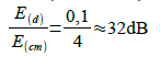
So, with this geometry, if we want the common mode signals do not appear evident in the differential reception, we need 32 "extra dB" of CMRR, to add insulation between modes (at least 30-40dB).
When you try to receive horizontal polarization, we must also keep in mind how the signals are generally lower than the vertical component, and then the "necessity" of CMRR also increases significantly.
From these initial observations, we can say that a CMRR of 80 dB is a reasonable requirement for all situations.
From this point of view, the performance of the component used (INA155) give us assurances. Unfortunately, as we shall see in the following, the values of the datasheet are "best case" and any external component to the amplifier ends to degrade the overall performance.
Continuing the analysis, the first elements to be put "under discussion" in these cases are the power supply line and the direct connection between antenna and receiver. Unfortunately, their liability is limited (but significant!) and also feeding the antenna with a battery on board and installing an electrically isolating transformer along the signal path do not improve dramatically the situation.
Serching for the guilty..
Said that, it remain the coaxial cable by itself to be investigated. But what role does play the cable? His "sin" is to connect the antenna to the receiver or there is "something else"?
Let slice the problem in smaller pieces and lets try to understand.
First, we redraw the circuit diagram, by inserting the elements sensors with their mutual capacity (C11 and C12), to the ground (C9 and C10) and the parasitic parameters of the structure, in particular the capacity to earth, synthesized in C8.
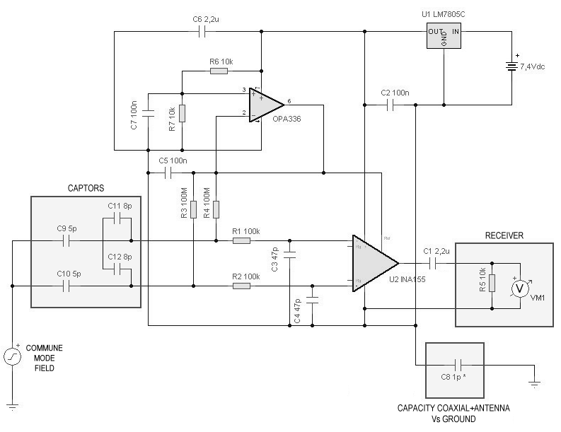
Wiring
diagram of the antenna with in evidence the capacity
to ground
The simulation (analysis of common and differential mode) for three values of capacitance to ground (1pF, 10pF, 100pF) gives us the following result:
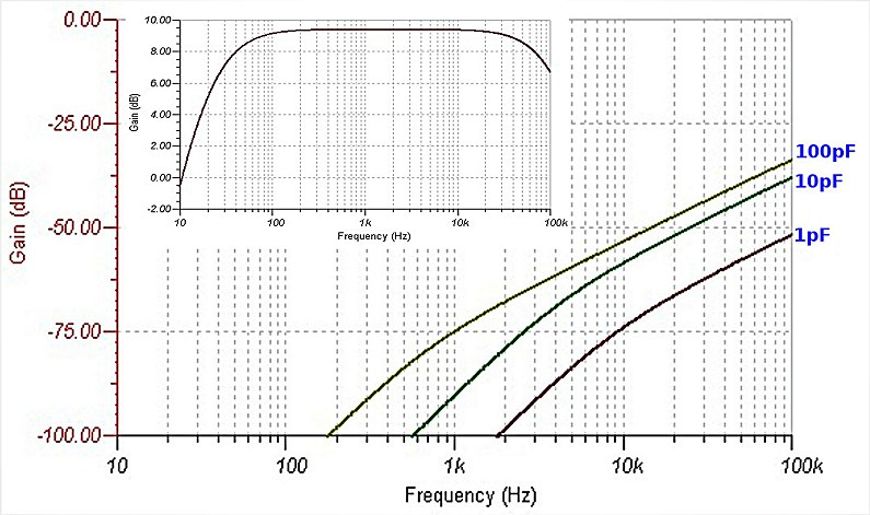
Frequency
response of common-mode antenna varying (1-10-100pF)
the capacity to ground.
In the box the frequency response in a differential way.
In the box the frequency response in a differential way.
It's clear that even a small capacity to the soil could degrade the CMRR even of tens of dB! (at 10kHz for example from 1 to 100 pF are 20dB, 32dB 2kHz!). If you think that 100 pF of parasitic capacitance are a lot, it may be worthwhile to note that the 10m of RG58 I use as a connection from the antenna to the sound card had approximately 120pF capacity to the ground!
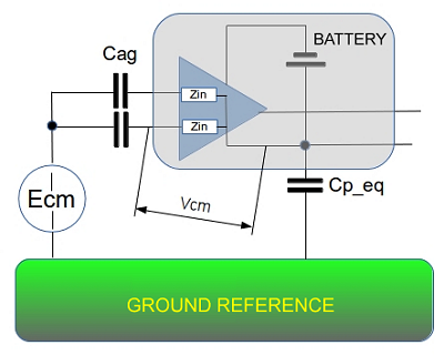
Why this behavior? Let us help usual with a sketch and some formulas.
 |
|
where:
Let try to describe the situation with the help of some equations, emphasizing the circuital parameters. For simplicity of writing, we define the value Cs as the capacity equivalent to the series of Cp_eq and Cag. |
The common mode signal (undesired) at the output of the amplifier will be:
Differential signal (wanted)

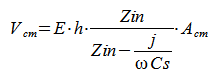
The optimal situation occurs looking for the maximum of the following function:

where:
- Zin: input impedance of the differential amplifier
- d: spacing of the sensors
- h: height of the sensors
- CMRRINA155: the CMRR of the instrumental amplifier
Unfortunately, even without developing more complex calculations, it is visible that "the blanket is too short" and any optimization of a variable will be in conflict some other(s).
It 'worth noting the following two ratios:
since the spacing of the sensors is always much smaller that the equivalent height

...decreases with increasing of Cp
which is equivalent to recognize that all the mechanical on constructive components of the antenna, go in the direction of reducing the CMRR of the real system.
A solution
Made clear this point, you can still look for suitable solutions to minimize these negative effects.
 |
|
If the actions on
the geometry of the antenna and its installation
can be quite intuitive and limited only by their
your imagination and building capacity, it is
interesting to see an optimal solution to minimize
the ability of the structure to the ground,
removing the coaxial cable that carries the signal
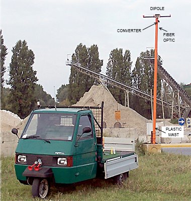
to the receiver. A big help comes from the world of audio, which now provides a very low cost analog-to-digital converter, with SPDIF optical digital output. An example is shown in the image. |
The new receiving structure becomes so composed:
- antenna
- A/D converter with optical output
- signal path into the optical fiber
- sound card with optical input
- Personal Computer
To verify the correct operation of the new system, you can perform the following tests:
1. vertical polarization antenna, amplifier standard configurationThis will configure the system to show us its behaviour in differential mode and common mode.
2. vertical polarization antenna, amplifier with the two inputs connected together at the same sensor
3. horizontal polarization antenna, amplifier standard configuration
The result obtained from the three tests, recorded in sequence in one screen is the following:
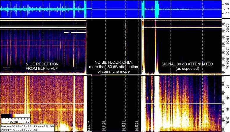
Spectrograms
of the three verification tests in sequence
Finally the antenna or better said, the receiving system, it actually works in differential mode!
Now, comparing vertical and horizontal polarization we can obtained an image of the received spectrum significantly different, as shown below:
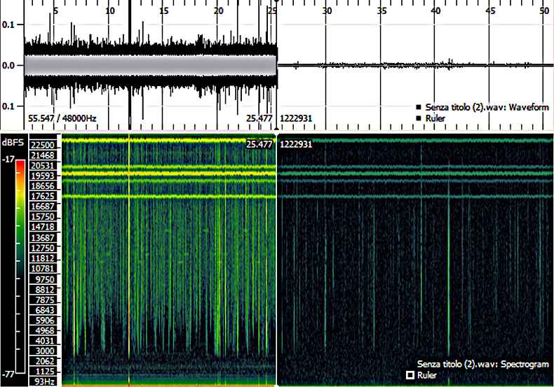
Vertical polarization (on left) and horizontal polarization (on right)
Final considerations and conclusions
The differntial structures may provide a "high potential of satisfaction" for the experimenters, as demonstrated by many tests and checks carried out. However, to operate truly differential (and hence give the advantages expected), must be "full floating", in other words, "very little coupled" with the reference plane, typically the ground.
One way to guarantee this result, is to remove all electrical and mechanical conductive connections conductive (support, power cords and signal cables) in the nearby of the antenna.
The ideal structure will be then characterized by:
- insulated antenna mounting
- self-powered (solar panel & on board battery for example)
- transmission of the digitized signal over an optical fiber
All this study has highlighted as the use of “short antennas" (or more correctly, electric field sensors) can not be separated by an accurate assessment of the installation and of the connecting elements and support.
Last but not least, I wanna thanks Renato IK1QFK for the critical spirit that led me to this study and its competent support.
Vy 73, Pierluigi
Return to vlf.it index