by J-M Polard (F5VLB) & M.Vallejo (EA4EOZ)
In the article, we presents a circuit that can solve a problem that sometimes compromises the operation of the VLF Receiver Software Toolkit. This happens when the PPS pulse duration of a GPS is not adequate, and the software programming of the device is not so simple. This is a relatively simple analog solution that solves the situation.
The problem and the solution
How long is the pulse in a PPS signal? If you test some GPS units, you will find very different values. Some GPS produce a 100ms long pulse, but other ones produce pulses in the millisecond or microsecond area. Usually, this is not a problem. A PPS signal works on the rising edge, so the circuit where the signal is used senses only the positive edge. In this way no matter how long the pulse is. It will work.
But some times, the PPS signal goes to a more exotic circuit or application and a too long PPS pulse can be a problem. One of these rare uses of a PPS signal is to synchronize audio streams using the VLF Receiver Software Toolkit. It records the PPS signal along with the desired audio, and then, using the recorded PPS signal along with the computer's clock, it adds precise timestamps to the audio stream.
It usually works well, but it can have issues if the PPS signal is too long:
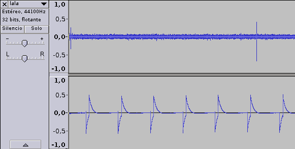
With the pulse completely distorted from the high pass (or DC-block, if you prefer!) of the sound card the vlftoolkit does not work at all. The solution? To shorten the pulse length. Probably there is a command for the GPS to configure the pulse length but not always it is easy to get the GPS to run that command, so the quickest way is to add an edge detector to conform the pulse to whatever length you want.

EA4EOZ build this circuit and it worked pretty well. I used a 74HC74 and a 74HC14, but probably other series, like HTC will work. You can replace the 74HC14 with a 74HC132 NAND gates with inputs joined together. The length of the pulse at the output can be adjusted with the aid of R and C. I used 22k and 20nF and I got a 0.8ms pulse length that works nicely with the vlftoolkit software.
As bonus, if the circuit uses TTL compatible logic (such us CD74HCT74, but not the CD74HC74), when supplyed at 5 volts, it can process both 3.3 and 5 volt PPS signals. To achieve this ambivalence, it is important to check on the flip-flop datasheet if its High-level input voltage (VIH) is less than 3V when the IC is powered at 5V.
To get maximum stability of delay time, it is important that the inverters have Schmitt trigger inputs.
To increase the repeatability and thermal stability of the circuit, it is necessary for the resistance R to be sufficiently high to keep the current supplied by the inverter away from its maximum value. The minimum value of R can be calculated whith this simple formula:
Rmin
= Vsupply / Io
Io is the Continuous output current, you can read it on the datasheet of the port. For example a 74HC14 has Io=25mA. Therefore, using it with a power supply of 5 V, the minimum value of the resistor is:
Rmin
= Vsupply / Io = 5 V / 25 mA = 200 Ohm
But using an old 74SL14 with Io of 0.4 mA, the minimum resistance must be 12.5 kOhm
This formula is very conservative, but it has the advantage of being simple and not too limiting, provided that "modern" logic gates are used.
Of course, this circuit adds a delay of a few tenths of ns, but working with sounds cards at sample rates under 1 MHz, this is not a problem at all.
The practical realization by F5VLB
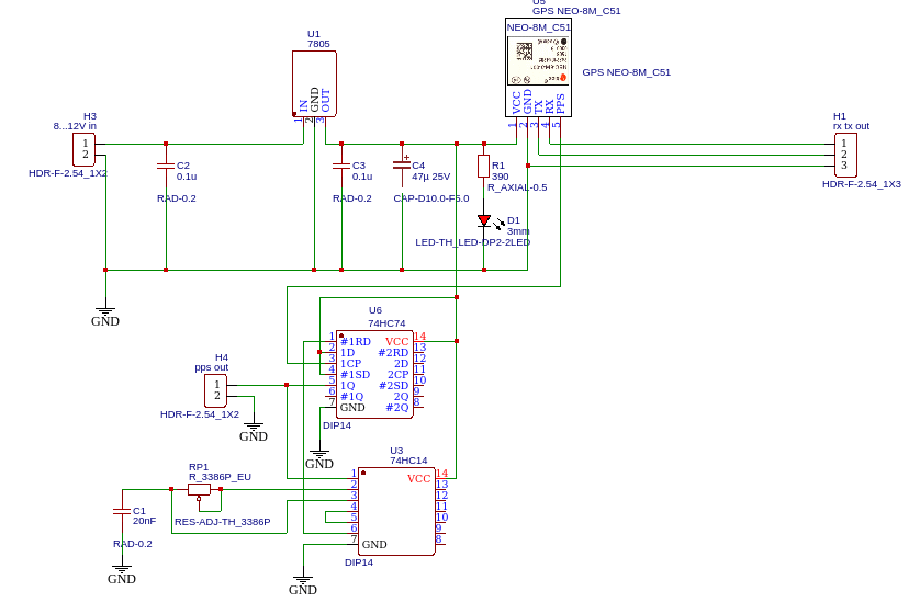
The diagram below is sufficiently explicit. We use a NEO-8N as a GPS module with an external antenna.
The time constant from RP1 / C1 determines the width of the pulse.
For the tests we used 47 KOhm / 20 nF. These values give us PPS pulses with a width of 0.17 to 0.82 ms sufficient for use with VLFRX Tools of Paul Nicholson.
Don’t spend time to calculate the time constant, start with these value and change the potentiometer if you need another range. The formula that relates the time constant to the pulse width is quite complex because it needs to account for the supply voltage of the gate and the thresholds of the subsequent Schmitt trigger, which are rarely precisely indicated on the datasheet. Because the threshold are function of the supply voltage, it is important to use a stabilized power supply.
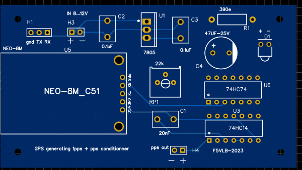
The price of printed circuits being democratized, a PCB has been made which makes the realization more practical. The H1 is just used for an RS232 talk with the module.
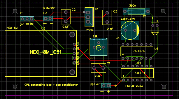
The PCB wired on the test table.
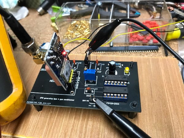
If you get a GPS module without connection pins, it can be mounted flat on the PCB. Take care to insert it correctly ! Some modules have to be mounted in mirror. A wrong connection can cause the destruction of the module
The test in the lab
Trying to measure the width of a PPS, which has a frequency of 1 Hz, can quickly become a nightmare. Keep in mind that these measurements are nearly impossible to perform with analog oscilloscopes. On current oscillos there is a mode called « Roll Mode » or « Scan Mode ». By making the Try and Go dance, we finally managed to see the PPS and measure its width.
Read the oscilloscope manual, where it is explained that when the horizontal time base control is typically set to 100 ms/div or slower, the instrument enters slow scan sampling mode, behaving like a plotter. Obviously, when using the slow scan mode (roll mode), to observe low-frequency signals, it is recommended to set the channel coupling to DC mode.
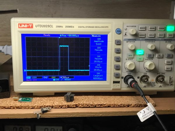
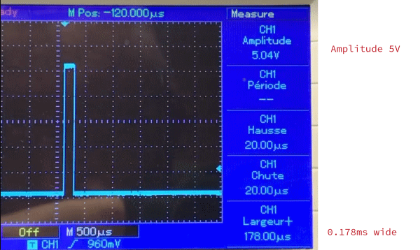
On this scope screenshot one can see amplitude of signal is 5V, width 0,178ms with potmeter at minimum.
If the pps of your gps module is 3,3V, no problem it will also work with this system.
On this scope screenshot one can see amplitude of signal is still 5V, width 0,820ms with potmeter at maximum.

Conclusions
A simple circuit, a few hours of work, but which can be of great use where the GPS does not cooperate in the right way. Contact us for any clarifications.
Return to www.vlf.it home page