XSP "X Signal
Prædactor" Receiver Front-end
By Gabriele
Seleri (IW2DWN)
Project Summary
-
Circuit design By
G. Seleri IW2DWN.
-
On-field preliminary testing
By
G. Seleri IW2DWN and C. Parmigiani IW2FER.
-
Data Analysis
By
G. Seleri IW2DWN and C. Parmigiani IW2FER.
-
Addendum: XSP Power Pack By
G. Seleri IW2DWN.
Circuit Design
I am currently working on
a very "smart" circuit, at the end of lab tests I will write down some
abstract about
the dimensioning of whole
receiving system. These are the lab measurements on the first stage of
the smart receiver (the one
which will be connected to the aerial):
| Channels separation |
120 dB |
| Noise |
6 dB |
| Dynamic |
90 dB |
| IMD |
-42 dBc (refferred to relative
value of -6.6dB) |
| CC Input impedance |
1,4 Mohm |
| AC Input impedance |
15 Mohm |
| Frequency response |
2 Hz - 20 kHz |
Below there are some screenshot
of the preliminary lab tests:
 |
|
IMD Graph with two tones, first tone 19 kHz, second
one 20 kHz, same amplitude.
Intermodulation distortion present at 1 kHz is
42 dBc under the main tones level.
Spurious Intermodulation products beside the mail
tones point out an even better IMD, about -44 dBc. |
|
|
|
 |
|
IMD Graph with two tones, first tone 2 kHz, second
one at 3 kHz, same amplitude.
Intermodulation distortion present at 1 kHz is
42 dBc under the main tones level. |
I have also noticed a lack
of circuit schemes, most of them are a carbon copy of each other.
Most circuits also use too
many op-amps. These amplifiers are good products but often does not fit
our
requirements because of their
input impedance, capacitance, slew rate and so on.
The brand new "smart" receiver
does not have a name yet, any suggestion ? I was thinking about something
like
"XSP - X Signal Prædactor"
(Yeah, it's "spaghetti" english/latin, logo design is in progress).
 |
Some resistor values have
been changed to match output impedance.
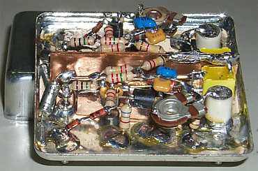
Circuit has been boxed into
an old TXCO case and it is very compact and robust. Insulated pass-thru
pins are ideal for our purposes and shielding is very good. Shielding is
good of course only for RF fields, there is no easy way to cut-off strong
ELF/VLF fields, i.e. 50 Hz.
|
The interference can be reduced
setting up (phisically) little circuit or by using SMD components.
The XSP core is based upon
the circuit proposed by Scott Fusare
in the document
"Some thoughts
on E-field Whistler receiver design" available at:
http://www.flash.net/~evogel/natrad2.pdf
All the changes in the schematic
has been done with the agreement of the author, who is also constantly
in contact with us.
On-field preliminary
testing
The circuit above has been
tested on three different sites, one of them is the same site we used to
test bikeloop. They are quiet places, with no harmful interferences caused
by broadcasting transmitters. These are the locations:
-
Gualdera near Fraciscio town
(22/06/02, province of Sondrio, 46°23.45'
N, 09°21.68' E, height 1830mt, WX sunny,
temperature about 28-30°C) [Track01,02]
-
Country road near Gualdera (22/06/02,
province of Sondrio, 46°24.08' N, 09°21.93'
E, height 1750mt, WX sunny, temperature about 28-30°C)
[Track03]
-
Prosto (23/06/02, province of Sondrio 46°19.50'N,
9°26.41'E, height 400mt, WX sunny, temperature about 28-30°C)
[Track04]
We choose these locations due
to the fact that active 50 Hz filter is not ready yet (!) and there is
not a massive urbanization.
We took four tracks, each
receiving scenario is described below:
-
Track01: XSP receiver powered
with single 12V source, Sony DAT recorder TCD-7, Bikeloop Antenna, ground.
-
Track02,03,04: XSP receiver powered
with single 12V source, Sony DAT recorder TCD-7, ground, antenna was made
by two huge insulated cables, each 2 mt. long, suspended to trees and insulated
from them. Both cables formed a "V" shape, with XSP located at the bottom.
The XSP has (actually) no gain,
it's just a front-end. Post-amplification of signals has been made by DAT
manual recording level control. This operation provides enough signal for
a good recording.
We pointed out immediately
a strong "Electrometer" effect, strongly reduced after a good grounding.
We are not going to explain this common electrostatic phenomena, but the
receiver is able to receiver people walking around the receiver, brushing
hair and so on.
A curious phenomena was the
reception of the wing-beat of flies and insects flying close to
the aerial. After a brief investigation (Many thanks to Renato Romero,
Scott Fusare and Michele D'Amico) we found out that insects are apparently
carrying often a small electrostatic charge. The exact charging mechanism
is not clear but it should be partially due to collisions with dust particles
while in flight, or air friction of the wings.
Scott Fusare wrote (summarized
):
"Some documents mention, for honey bees, accumulated charge from 30 - 90
pC and as you point out the structural or "isotropic" capacitance of the
insect's body is tiny. If we used the old trick of approximating the insect
as a sphere we could calculate it, it'll be in the femtofarads if I am
recalling the formula correctly. Better yet, let me look it up...
OK that's 4*Pi* epsilon
naught*radius(meters) , as a guess the bee would be .5 cm in radius
so that's 55 femtofarads. 50 pC / 55fF = 898 volts! That's just a very
rough guess of course. How much of that is on the wings I don't know, but
certainly enough that the beating of the wings can couple a signal into
the antenna.
The moving wing will form
one "plate" of a capacitor, the antenna the other.
As the wing moves the capacitance
changes (slightly) and modulates the voltage being induced through the
antenna by the current fluctuations.
I = C*dV/dt + dC/dtV
the second term in the derivative (which is usually forgotten) is at work
here.
By the way, I have been unable
to find any confirmation of my predicted voltage in the literature".
Signals above were recorded
in different places and in different days, this means that is a common
phenomena. There seems to be also a correlation between the length of the
aerial and the dimensions of the insects recorded. Little antennas (1 meter)
allow reception of smaller insects, with longer antennas (i.e. big Marconi
aerial) the phenomena disappear.
By the way, this is what we
call "Nature Radio"... click HERE to hear an
example (150 kb).
Many other signals were present,
sferics, high-pitched tones and so on.
Here follows the analysis
of the tracks.
Data analysis
This time the tracks were
not been resampled at 44,1 kHz but left at 48 kHz, the files have been
saved on CD as wave data files, so it's possible to postprocess signals
up to 24 kHz.
First track [Track01] was
a test. The AC input impedance of XSP is about 15 Mohm, the bikeloop magnetic
antenna has a low impedance, this means that input is (more or less) shorted
to ground. This means also a great noise.
Regardless of this hypothesis
some statics have been received showing the high sensitivity of the device.
[Track01] did not show strange or unusual signals.
Second track [Track02] pointed
out the high sensitivity of XSP. High level man-made noise is also present.
Here follows a spectrogram
for the band 10 - 24 kHz, taken from [Track04]:
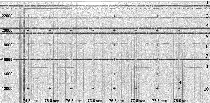
Many sferics are present,
man-made signals have been identified as follows:
1
- 23400 Hz - DHO30,
Navy Ramsloh (D) RTTY 200 baud.
2
- 23000 Hz - Russian
BETA Time signal marker, followed at the and by carriers on 22900 and 22500
Hz, probably correlated.
3
- 21750 Hz - HWU,
Navy Le Blanc (F) RTTY 200baud.
4
- 20300 Hz - ICV,
Tavolara Island, Sardinia (I).
5
- 19600 Hz - GBZ,
Criggons (GB).
6
- 18200 Hz - VTX3,
Indian Navy Traffic Station, CW callsign correctly identified.
7
- 16000 Hz - GBR,
Rugby (GB).
8
- 14881 Hz - Alpha,
Ex-USSR radionavigation system.
9
- 12650 Hz - Alpha,
Ex-USSR radionavigation system.
10 -
11905 Hz - Alpha, Ex-USSR radionavigation
system.
On other tracks others man-made
signals has been identified, for example:
[Track03]
16400 Hz - JXN, Noviken, Norway, signal
disappears after 14'17''.
[Track03]
18100 Hz - UQFE, Ex-USSR, several RTTY
transmissions.
[Track04]
20500 Hz - Received carrier from 22'42''
to 27'26''. Frequency appears to be used from 3SA/3SB, Datong, China Naval
Base.
Now, let's have a look below
10 kHz.

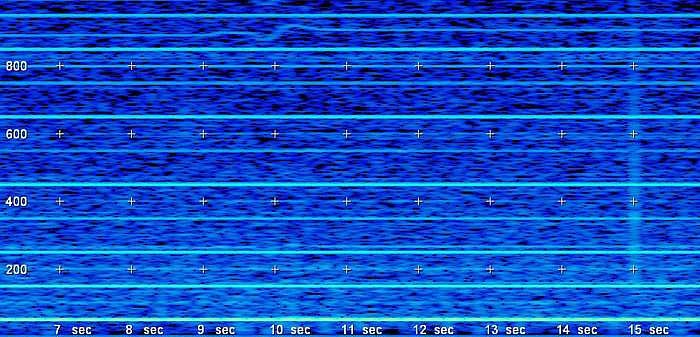
No interesting signals have
been received, all lines are man-made noise, the only noticeable thing
is a fluctuation of the 900 Hz tone, origin and explaination are unknown.
There are many other strange
signals, fluctuations of 50 Hz main hum produces harmonics up to 800 Hz
and appears like some kind of AFSK transmission, but they are not.
These fluctuations could
be caused by asymmetric and/or unbalanced loads on three-phase distribution
lines.
Currently we do not have any
filter for 50 Hz. It has been designed but not built yet.
We did not receive any activity
on Schumann frequencies, nor on 76 and 82 Hz band.
Probably the input impedance
of XSP is still too low to record them with short aerials. We are working
on a second front-end circuit with (even) a higher impedance.
With this second circuit
we will also be able to connect our Bikeloop magnetic antenna.
Summarizing, these will be
the next steps in the "XSP" Project:
-
Construction of the second front-end
and lab/on-field comparison with the first prototype, expecially in the
ELF/ULF range.
-
Construction/assembly of circuitry
for differential input.
-
Test with magnetic and/or electrical
antenna.
-
Construction and optimization
of 50 Hz active filter.
-
Construction and optimization
of power circuits, expecially concerning dual feeding and cabling.
XSP Power Pack
By Gabriele
Seleri (IW2DWN)
The XSP Receiver is a portable
all-purpose receiver. This means of course that it needs electrical power.
In the next future, receiver
will need a dual voltage, so I decided to assembly this simple box, which
can be also used for a moltitude of other applications, such as amateur
radio, CD player and so on.
At the beginning, these were
my action-points about it:
-
Not excessively cumbersome nor
too heavy,
-
Single and dual voltage,
-
Heavy duty,
-
Rechargeable,
-
Easy maitenance
-
and not too expensive, as usual.
As main power source I used two
sealed Pb-gel batteries, 12V, 1.2 Ah. I preferred Pb-gel instead of Ni-MH
or Ni-Cd because these kind of battery can be easily recharged with power
supply in my shack without complicated circuits. I did not even consider
Li-ion batteries, for the high cost of cells.
 |
|
This is the finished artifact. Red round switch
is the main one. It supply power to all the terminals (gold plated). Metallic
switch on the right of the green LED is used to connect batteries in parallel
or not. This cause output to be:
-
+6V, -6V, +12V and GND or:
-
+12V, -12V, +24V and GND
depending on the nature of load connected.
Bargraph it's a voltmeter (0.8 V each segment).
It has been calibrated to be completely off when batteries are discharged
(18V). Full scale voltage is about 25V.
Useful to keep batteries in health. |
Two big heat dissipater have been provided for the
BD-711/712 transistor, clearly visible.
Enclosure is a Teko CP3 (160×96×67mm)
Power pack schematic.
As many things, this schematic
has been drawn one evening during a dinner on a paper napkin. The picture
is a scanned bitmap of the original (still in my pocket), so it is not
perfect.
The circuit is very simple,
S1 is a double switch (A and B), I is the main single Switch, LD is a LED
who lights on when batteries are connected in series.
Rec is a female-RCA plug
used to recharge batteries. (V) is the voltmeter.
The Op-Amp ua741 is referenced
to Vcc/2. The two transistors are connected to form an "active voltage
divider".
In this configuration transistors
works to mantain the "virtual GND" voltage equal to the voltage applied
on to the non-inverting input of the Op-Amp.
This will cause the "virtual
GND" terminal to be always at Vcc/2.
 |
|
Circuit has been tested with
a continuous 2A load on a single leg (the most critical situation) without
any problem or overheating.
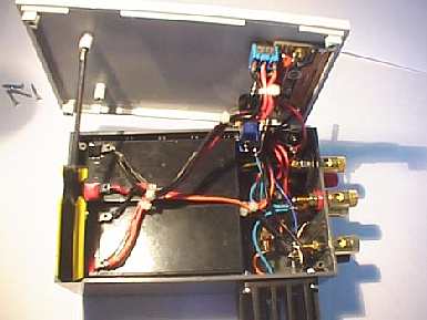
This is a pic or the the internal wiring of XSP-PP.
The size of Teko enclosure match perfectly with the size of the two batteries.
Total weight is less than 1 kg. |
This is our idea of "Portable power pack", performances
and circuitry could be enhanced, of course, but until now it's a cheap
and reliable solution.
Stay tuned for further info
about "XSP" project...!
Feedbacks/comments are welcome!
Write us at: gseleri@sente.it
or iz2fer@tiscali.it
Many thanks to Renato Romero,
Michele D'Amico and Scott Fusare for all informations about "electrostatics
flies".
Return to the main
index