THE B3CKS VLF - ANTENNA PROJECT
15Hz-30kHz
reception in grounded or floating mode
by Torsten Heer - DKS302 - Germany
DEUTSCHE VERSION
One night I saw two beer cans on my workbench, and they remember me at the
Floating Solar Receiver by Renato Romero. I figured, why not? These two
cans are nothing more than capacitors. So there is a chance to use them
in combination with a condenser microphone amplifier for a VLF Receiver.
Bingo... The first tests as a Monopole gave good results.
With very satisfactory results I begin another test.
Reception at my location:
| I live in a small town located at J041VG with approximately 7500 inhabitants.
The height above sea level is between 220-650 m over NN. My QTH is in the middle of town and 330 m over NN. All the
mountains and the buildings are higher than my QTH. To top it all I have many signals interfering with VLF reception
such as power line hum, broad-band RF and possibly modem or cable TV interference. I hear many signals from the VLF
band up to 108MHz. Certainly not good for VLF listening. I've tried numerous types of Antennas but so far not much
satisfaction. The Magnetic type antennas (ferrite and loop) give good reception of sferics, but, unfortunately too
much hum and RF. All attempts to blank out this interference reduce the sound quality of the sferics. So I tried
different electric antennas. With some of them I was able to listen to the VLF band without too much hum and interference
at my QTH. Unfortunately I do not have the room to put up large antennas. The receiving of sferics is shielded by building
around me and the broadband signals produce an incredibly loud background noise. The bulk of the interference is between
3.5KHz to 6.5KHz and 8KHz to 11KHz. No other options. I must go out to open country. |
|
 |
THE BEER CAN ANTENNA PROJECT
This is a picture of the first test construction. The gap between the cans is around 60mm.
The first test of the antenna gave a very good result... ...until sundown! Suddenly I heard
many Radio Stations from different Countries and the signals faded in and out in varying cycles. So I was frustrated
by this and went to bed. But someone :-) told me: "You have to change the capacitors in the circuit...."
THE ORIGINAL CIRCUIT
The circuit is built up around a TL072 op-amp. This circuit was sold by ELV.
ELV-Elektronik
Original Schematic Diagramm MIC - VV |
The circuit is modified by changing C4 & C7 to 1.5nF to block the RF signals and adding 15nF
to R10 in series. Also to compensate the impedance from the input to the beer cans R4 and R9 are replaced with a 10M
resistor. The bridge 1 between ST3 & ST4 is not used. If the bridge 1 is closed the amplifier will support a current for
electret microphones. Bridge 2 is also not used. The circuit can be powered by a single supply between 5 and 15 volts.
I use a 9 volt battery. The amplifier provides enough signal to drive the line input to the PC soundcard and produce
relatively little noise. So you can use the other channel for instance with a magnetic antenna.
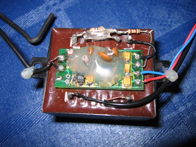
THE MODIFIED CIRCUIT

Schematic after modifications |
The output of the amplifier is connected in series with a 690 ohm resistor to the 24V side of
little transformer. The 230V side is connected across a 10K, 10 turn, potentiometer. In series with a 2.5K resistor so
he resistance is variable from 2.5K up to 12.5K. So you can search for the best level for the input to the soundcard.
he value of the resistance depends on the transformer. To change from floating mode to grounded mode add a switch between
he minus of the battery and the ground wire to the soundcard.
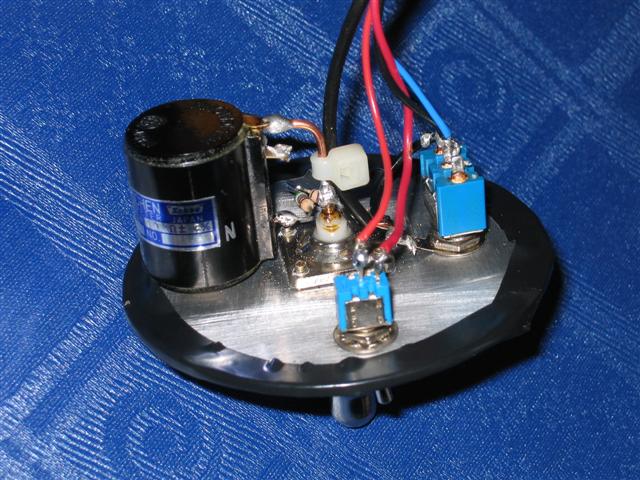
THE MOUNTED B3CKS - ANTENNA
A picture of the finished B3CKS VLF-Antenna
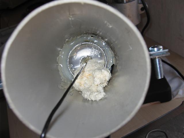
The antenna is mounted in a 76mm downspout. The length amounts to 55cm. The beer cans are glued
with hot-glue in the downspout. The top is covered with a cap and is filled with silicon. The wire runs through the lower
an down to the amplifier and it is possible to pull out of the downspout for 10cm. This made it easy to repair the amplifier
or to make changes before the final mounting. The connector plate is mounted 4cm inside the pipe to protect against rain.
The right picture shows the connector plate. On the plate are mounted the power switch, the switch to change between grounded
and floating mode, the BNC output and the 10 turn potentiometer.
THE RESULTS
This antenna does not have to hide from other antennas. The construction is
very simple and the materials are very cheap!
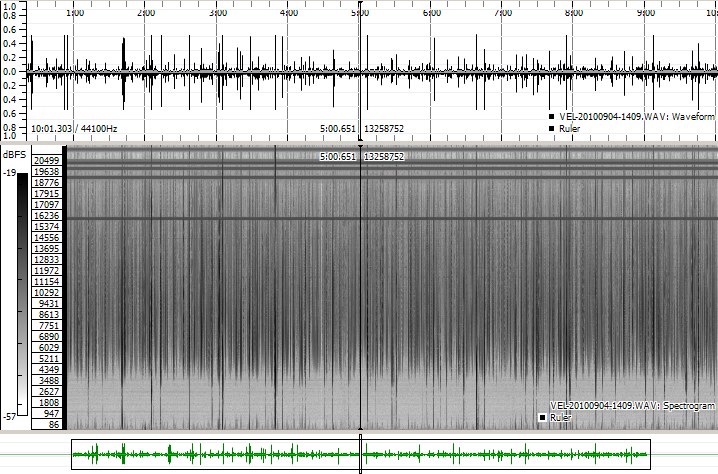
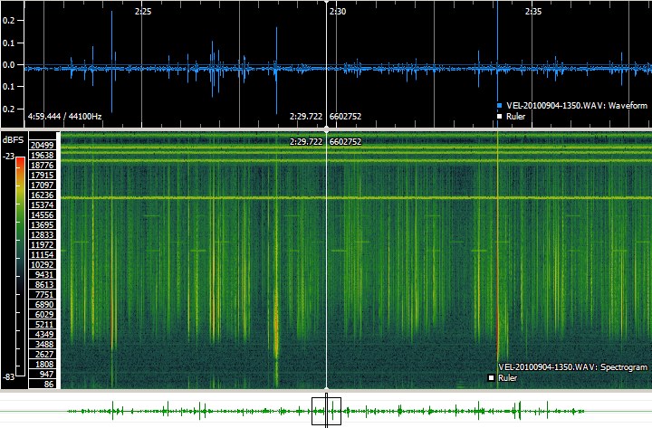
This recording is not filtred
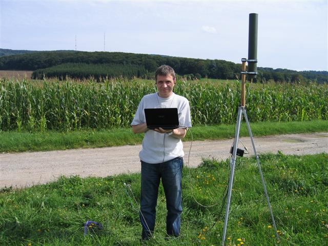
by any Soft- or Hardware- Filter, and was made in the fields near by the village!
The Spectogram displays clearly the Alphstations.
And I think it would be possible to receive the SAQ transmitter with this antenna.
This is a nice and cheap weekend project with quick and excellent results. All in one...it works
very well.
THE CONSTRUCTION
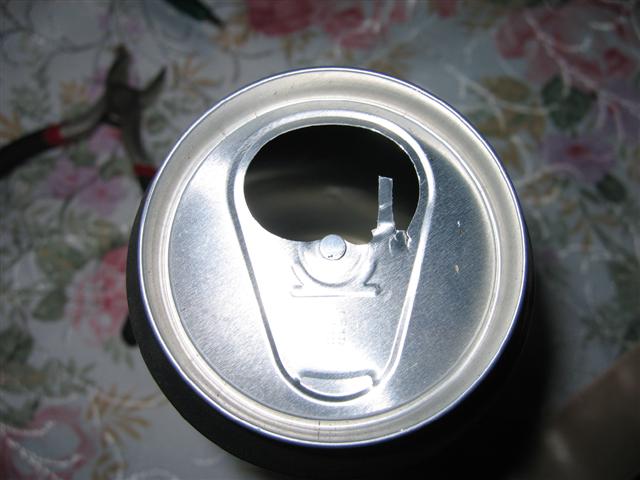
At first remove the pull ring and bend out the tab.
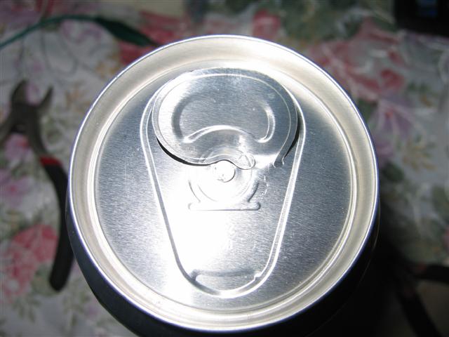
Cut a strip out of the tab for a connector.
Connect a lustre terminal
Drill a hole in the bottom of the beer can; push the cable through the
beer can and glue it in place. Connect the ground wire at the lustre terminal and fix it with glue.

Connect the ground wire at the lustre terminal and fix it allso with
glue.
Attention: Newer beer cans may not have electrical connection from the
top rim to the can. Crimp together as pictured.

Cut a strip from a toilet paper roll to
50mm and glue it to the lower can. Connect the hot wire to the upper can and glue the cans together.
Glue the cans to the downspout.
Connect the wires to the circuit.
Then connect the wires to the plate.
Mount the transformer and the circuit
with expanding foam to the downspout.
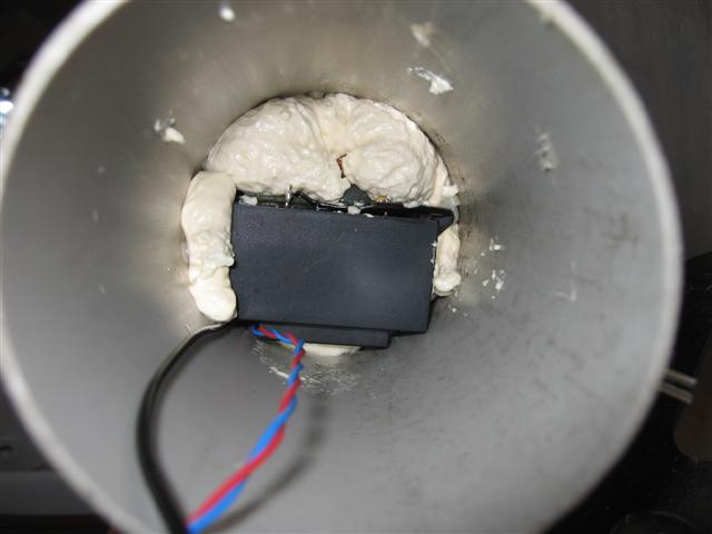
Push the battery and the connector plate
into the downspout. Now you are ready to receive.

Recording in a field.
Many thanks for Renato's Help
A little audio file (unfiltred)
Listen to the file in MP3 format here. 60 seconds. 939 KB:
EPT-20100814-1420.mp3
Thanks for reading this. 55, 73, Torsten-DKS302
Check allso my YouTube site: KLICK
Or take a look at Funkforum: KLICK
Return to the main Index